Zoom lens system

a zoom lens and lens body technology, applied in the field of zoom lens systems, can solve the problems of difficult manufacturing, high sensitivity to decentering, and insatiable correction of aberration

Inactive Publication Date: 2004-08-05
NIKON CORP
View PDF5 Cites 11 Cited by
  • Summary
  • Abstract
  • Description
  • Claims
  • Application Information

AI Technical Summary

Benefits of technology

[0009] The present invention is made in view of the aforementioned problems and has an object to provide a zoom lens system having compactness of about the size of a single focal length normal lens, small number of lens elements, zoom ratio of about 2.9, and high optical performance with being easy to be manufactured.

Problems solved by technology

However, the zoom lens disclosed in Japanese Patent Application Laid-Open No. 55-60911 is bulky and correction of aberration is not satisfactory.
The zoom lenses disclosed in Japanese Patent Application Laid-Open Nos. 8-334694 and 2002-6214 have a large number of lens elements and are difficult to be manufactured.
Moreover, the zoom lenses disclosed in Japanese Patent Application Laid-Open Nos. 9-171140 and 2000-2837 have a large number of lens elements, so they are bulky.
However, the lens having any of these lens types has a large deviation angle upon refracting each light ray at each lens surface, so it has a defect that the sensitivity to decentering is high.
In other words, when it is manufactured, accuracy of each part has to be increased upon processing and accuracy of adjustment has to be increased upon assembling, so that it has a defect to increase manufacturing cost.
Accordingly, it becomes difficult to correct aberrations or to accomplish high optical performance, an increase in productivity, lowering manufacturing cost, and compactness.
Accordingly, it becomes difficult to accomplish high optical performance, an increase in productivity, lowering manufacturing cost, and compactness.
However, this is against reduction of production cost, and compactness, so that it is undesirable.
Therefore, each lens element in the front lens group G.sub.2-1 becomes sensitive to decentering, so that it becomes difficult to accomplish an increase in productivity, a decrease in manufacturing cost and compactness.
Moreover, spherical aberration and upper coma becomes worse, so that it becomes difficult to correct aberrations.
Furthermore, the second lens group tends to become large.
Accordingly, it becomes difficult to accomplish high optical performance, an increase in productivity, a decrease in manufacturing cost and compactness.
Moreover, it becomes difficult to correct spherical aberration, so it is undesirable.
Therefore, it becomes difficult to correct astigmatism and curvature of field, and as a result, it becomes difficult to make the lens to be wide-angle.
Moreover, it becomes difficult to correct spherical aberration, so it is undesirable.
Therefore, it becomes difficult to correct astigmatism and curvature of field, and as a result, it becomes difficult to make the lens to be wide-angle.
Accordingly, when conditional expression (5) is not satisfied, a zoom lens system having an extremely few number of lens elements in the first lens group including a wide-angle range with compactness and good productivity cannot be accomplished.
Accordingly, when conditional expression (6) is not satisfied, a zoom lens system having an extremely few number of lens elements in the first lens group including a wide-angle range with compactness and good productivity cannot be accomplished.

Method used


Image

  • Zoom lens system
  • Zoom lens system
  • Zoom lens system

Examples


example 2

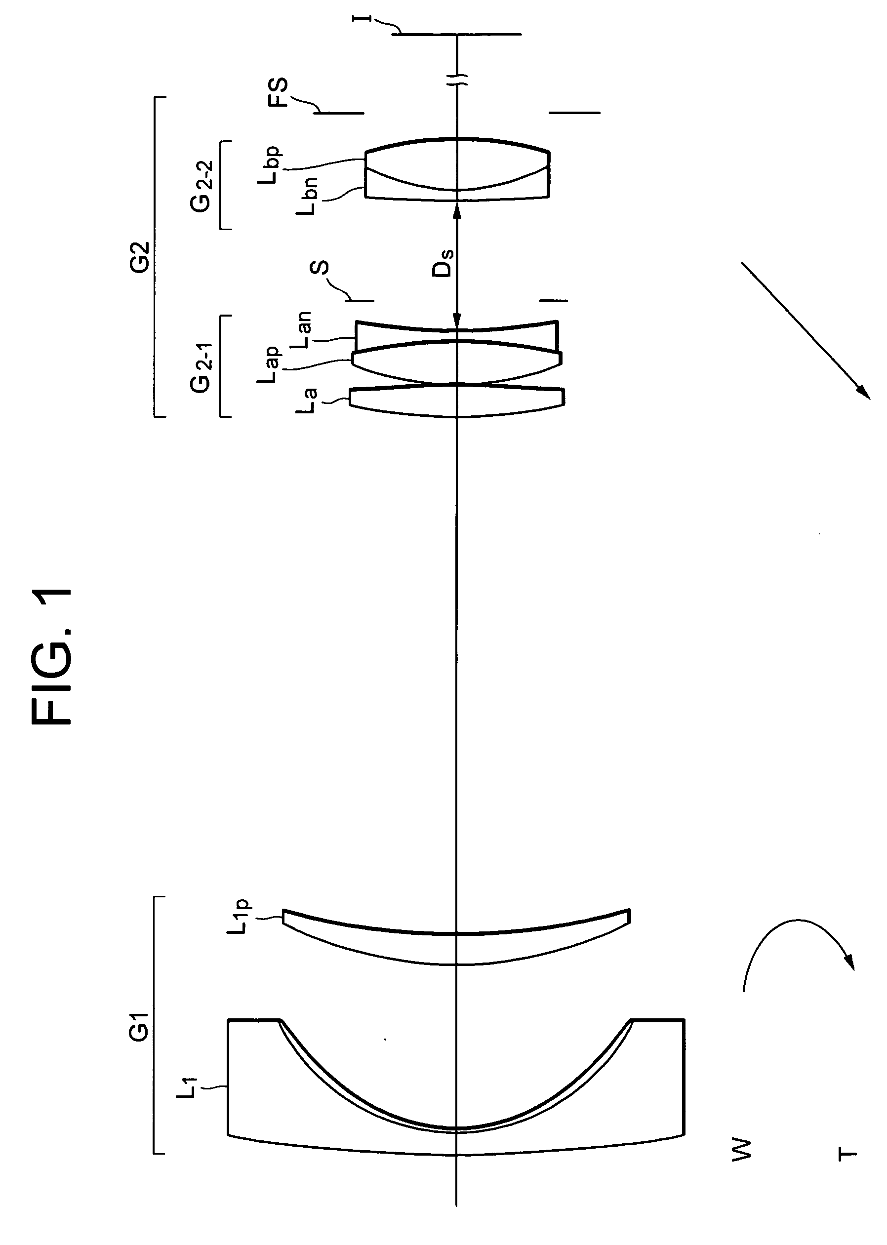
[0092] FIG. 5 is a diagram showing the lens arrangement of a zoom lens system according to Example 2 of the present invention together with movement of each lens group.

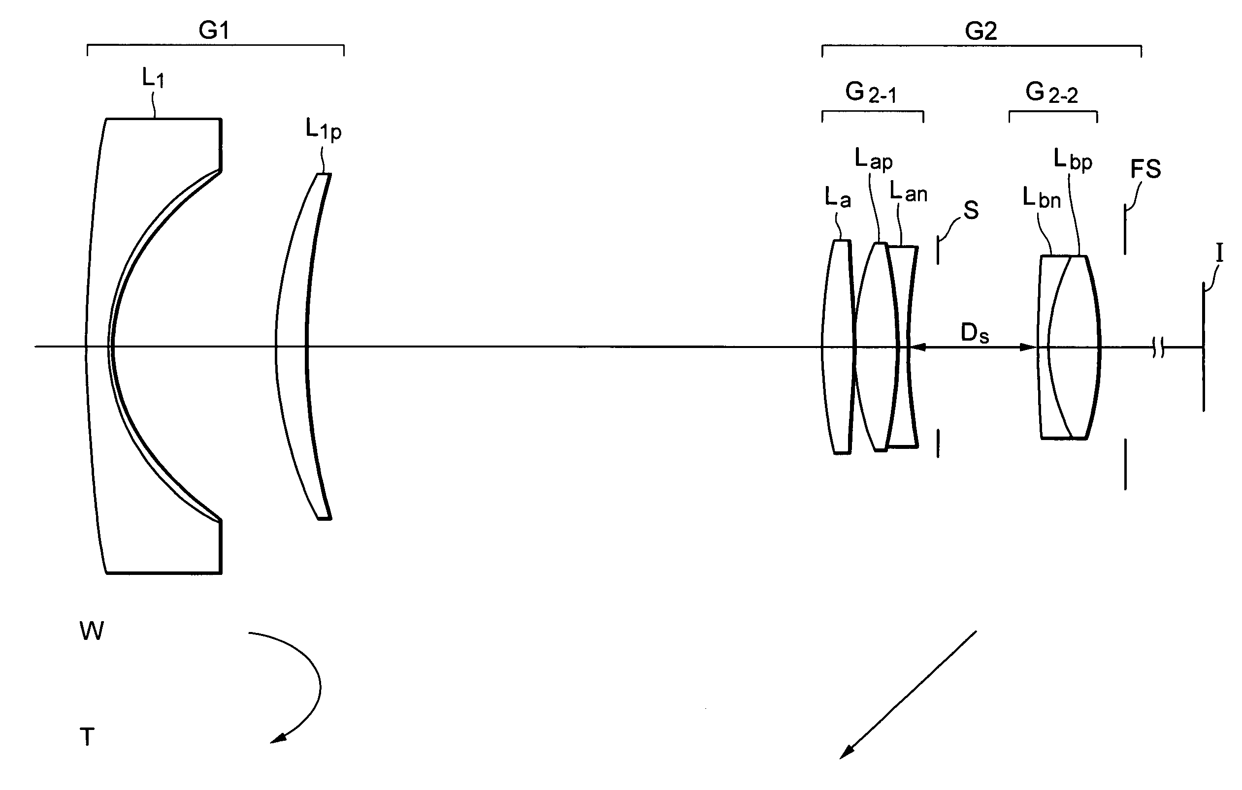
[0093] The zoom lens system according to Example 2 is a negative-positive two-group zoom lens system composed of, in order from an object, a first lens group G1 having negative refractive power and a second lens group G2 having positive refractive power.

[0094] The first lens group G1 is composed of, in order from the object, a negative meniscus lens L.sub.1 having a convex surface facing to the object, and a positive meniscus lens L.sub.1p having a convex surface facing to the object. The negative meniscus lens L.sub.1 is a compound lens constructed by glass and resin. Resin is arranged on the image side surface of the lens. The image side surface of the resin is an aspherical surface.

[0095] The second lens group G2 is composed of, in order from the object, a front lens group G.sub.2-1, an aperture stop S, a rear lens...

example 3

[0103] FIG. 9 is a diagram showing the lens arrangement of a zoom lens system according to Example 3 of the present invention together with movement of each lens group.

[0104] The zoom lens system according to Example 3 is a negative-positive two-group zoom lens system composed of, in order from an object, a first lens group G1 having negative refractive power and a second lens group G2 having positive refractive power.

[0105] The first lens group G1 is composed of, in order from the object, a negative meniscus lens L.sub.1 having a convex surface facing to the object, and a positive meniscus lens L.sub.1p having a convex surface facing to the object. The negative meniscus lens L.sub.1 is a compound lens constructed by glass and resin. Resin is arranged on the image side surface of the lens. The image side surface of the resin is an aspherical surface.

[0106] The second lens group G2 is composed of, in order from the object, a front lens group G.sub.2-1, an aperture stop S, a rear lens...


PUM


Abstract

An object is to provide a zoom lens system having compactness of about a normal lens, small number of lens elements, a zoom ratio about 2.9, good productivity, and high optical performance. The system includes, in order from the object, a first lens group with negative power and a second lens group with positive power. Zooming is performed by varying a distance between the first lens group and the second lens group. The first lens group includes at least a negative lens and a positive lens. The second lens group includes a front lens group with positive power and a rear lens group with positive power. The front lens group includes a positive lens and a cemented lens constructed by a positive lens cemented with a negative lens. The rear lens group includes a cemented lens constructed by a negative lens cemented with a positive lens. Given conditions are satisfied.

Description

[0001] The disclosures of the following priority application is herein incorporated by reference:[0002] Japanese Patent Application No. 2003-016603 filed Jan. 24, 2003.[0003] 1. Field of the Invention[0004] The present invention relates to a zoom lens system.[0005] 2. Related Background Art[0006] Among negative-positive type two-group zoom lenses, there is a zoom lens using an advanced Gauss type lens group as a second lens group having positive refractive power (disclosed, for example, in Japanese Patent Application Laid-Open No. 55-60911). In addition, zoom lenses of this type have been disclosed, for example, in Japanese Patent Application Laid-Open Nos. 8-334694, 9-171140, 2000-2837, and 2002-6214).[0007] However, the zoom lens disclosed in Japanese Patent Application Laid-Open No. 55-60911 is bulky and correction of aberration is not satisfactory. The zoom lenses disclosed in Japanese Patent Application Laid-Open Nos. 8-334694 and 2002-6214 have a large number of lens elements ...

Claims


Application Information

Patent Timeline
Patent Type & Authority Applications(United States)
IPC IPC(8): G02B15/16G02B13/18G02B15/14G02B15/177
CPCG02B15/177G02B15/14G02B15/1425
Inventor SATO, HARUO
Owner NIKON CORP
Why Eureka
Try Eureka