Method for producing granulated powder of r-fe-b type alloy and method for producing r-fe b type alloy sintered compact

Inactive Publication Date: 2004-08-05
HITACHI METALS LTD
View PDF9 Cites 2 Cited by
  • Summary
  • Abstract
  • Description
  • Claims
  • Application Information

AI Technical Summary

Benefits of technology

0063] According to the present invention, in which a granulated powder excellent in flowability and compactibility is used as described above, the powder can be loaded into the cavity uniformly with a reduced variation in loading amount. Therefore, variations are small in the mass and size of the compacts obtained by the compaction. Also, chips and fractures are less forme

Problems solved by technology
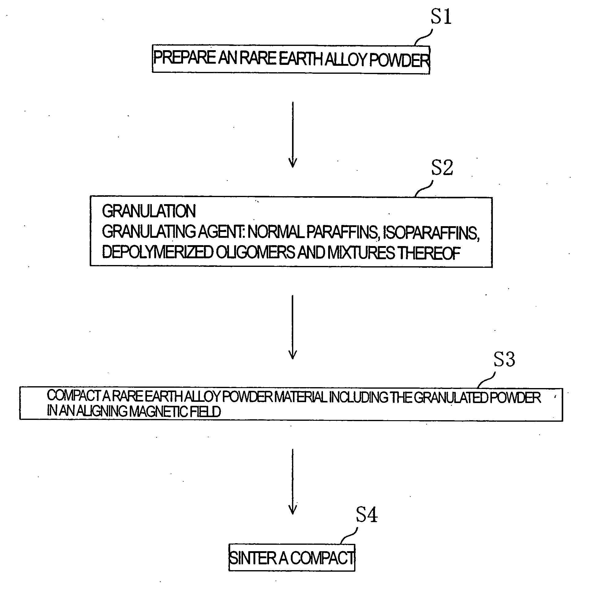
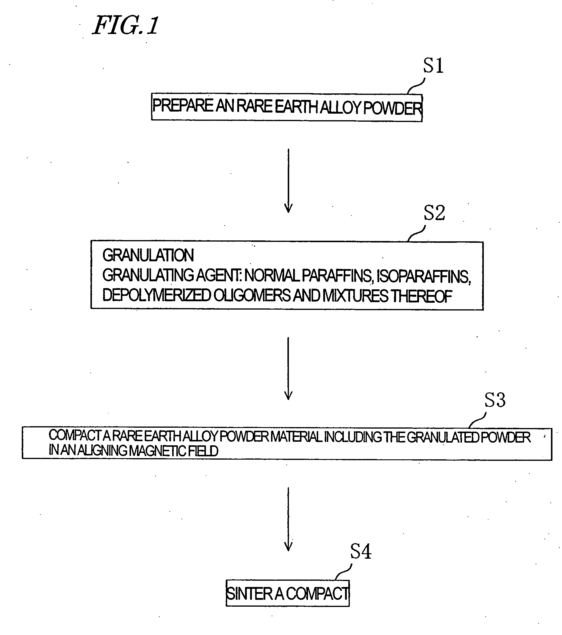
A powder having such a small mean particle size is however poor in flowability and compactibility (including cavity loading capability and compressibility), and thus poor in productivity.
Use of a lubricant described above contributes to some degree of improvement, but fails in imparting sufficient compactibility.
In particular, a powder prepared by the strip casting process, which is not only small in mean particle size but also narrow in particle size distribution, is especially poor in flowability.
This causes problems such that the amount of powder loaded in a cavity tends to vary beyond an acceptable range, and that the loading density in the cavity tends to lack uniformity.
As a result, the mass and size of the resultant compact may vary beyond an acceptable range, and chips and fractures may be formed in the compact.
The granulating agent disclosed in Japanese Laid-Open Patent Publication No. 63-237402 described above is poor in removability.
Therefore, in the case of production of an R--Fe--B sintered magnet, the magnetic properties disadvantageously degrade due to carbon remaining in a sintered body.
The resultant granulated powder is too rigid to disintegrate under application of an external magne

Method used


Image

  • Method for producing granulated powder of r-fe-b type alloy and method for producing r-fe b type alloy sintered compact
  • Method for producing granulated powder of r-fe-b type alloy and method for producing r-fe b type alloy sintered compact
  • Method for producing granulated powder of r-fe-b type alloy and method for producing r-fe b type alloy sintered compact

Examples


Example

[0073] As for the granulated powders in Example 12 and Comparative Examples 6 and 9, the variation (%) in the mass of the compact and the variation (.sigma.) in loading amount were evaluated. The variation in the mass of the compact was calculated from {(maximum mass-minimum mass) / mean mass (n =50)}.times.100 (%). The variation (.sigma.) in loading amount represents the standard deviation of the mass distribution of 50 compacts. The results are shown in Table 4.

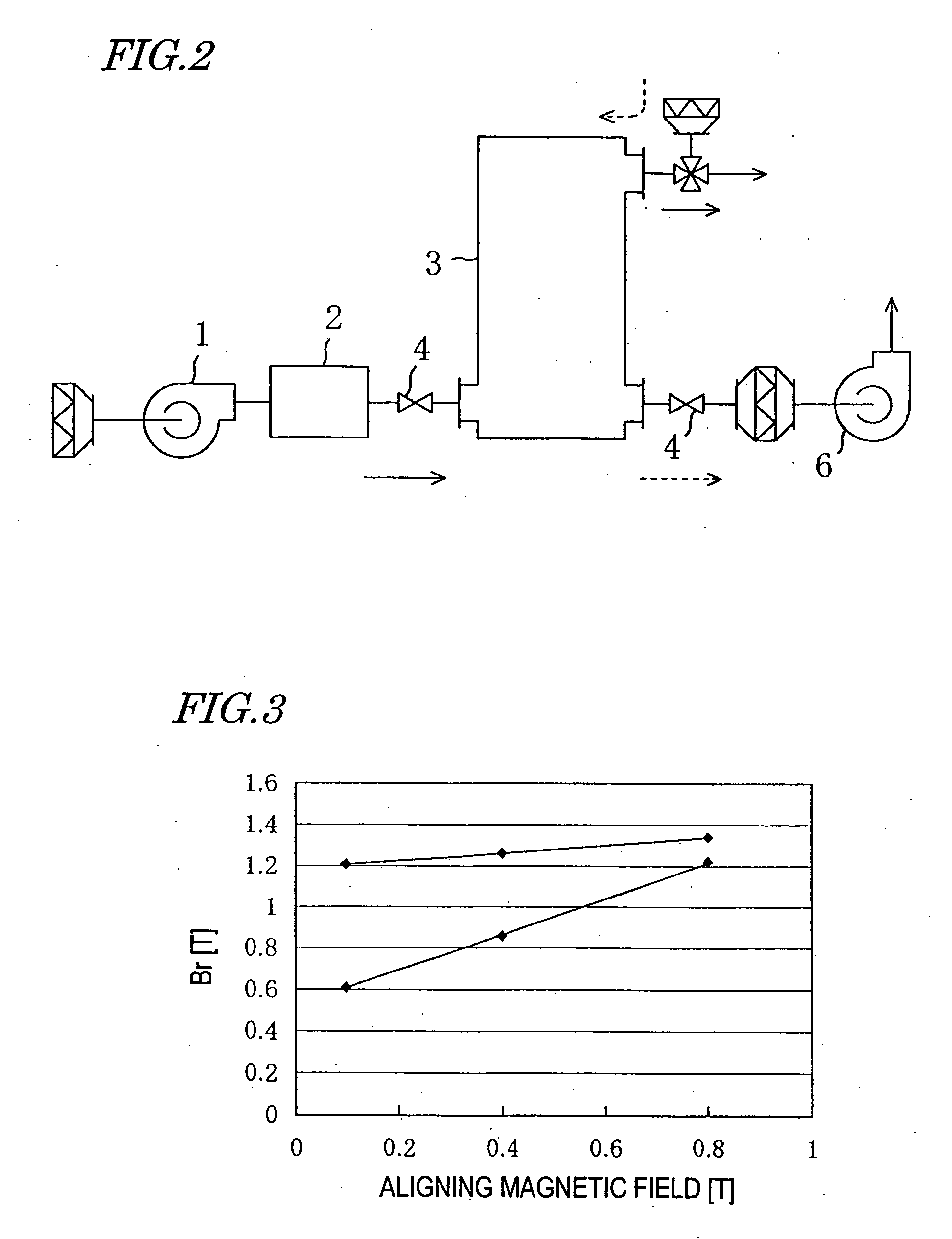
[0074] As for the granulated powders in Example 12 and Comparative Examples 6 and 9, also, the magnetic field alignment property was evaluated, in which the magnetic flux density of the aligning magnetic field applied in the compacting step was changed from 0.1 T to 0.4 T and 0.8 T, and the magnetic properties (remanence Br and cohesive force iHc) of the resultant sintered magnets were evaluated. The evaluation results are shown in Table 4 and FIG. 3. FIG. 3 is a graph obtained by plotting the magnetic flux density of the ali...

Example

3TABLE 3 Composition of granulating agent Com Com Com Com Com Com Com Com Com (molecular weight) / mass % Ex. 1 Ex. 2 Ex. 3 Ex. 4 Ex. 5 Ex. 6 Ex. 7 Ex. 8 Ex. 9 Normal hexane (86) 100 90 50 90 -- -- -- -- --Polybutene (650) -- 10 50 -- 3 -- -- -- --Polybutene (1000) -- -- -- 10 ---- -- -- --Liquid paraffin -- -- -- -- 97 -- -- -- --Polyvinyl alcohol (PVA) -- -- -- -- -- 100 100 100 --Added amount (mass %) 2.0 5.0 5.0 2.0 2.0 2.0 5.0 10.0 0.0 Granulation capability X .largecircle. .largecircle. .largecircle. .largecircle. .largecircle. .largecircle. .largecircle. X Removability .largecircle. X X X X X X X .largecircle.

[0077]

4 TABLE 4 Example 12 Comparative Ex. 9 Comparative Ex. 6 Aligning 0.1 0.4 0.8 0.1 0.4 0.8 0.1 0.4 0.8 magnetic field(T) Br (T) 1.20 1.26 1.34 1.21 1.26 1.35 0.60 0.85 1.22 iHc (kA / m) 1261 1185 1139 1240 1200 1135 1250 1211 1145 Variation in 5.4 14.6 4.6 Mass of Compact (%) Variation in 0.18 0.33 0.16 loading (.sigma.)

[0078]

5TABLE 5 Item Ex. 1 Ex. 2 Ex. 3 Ex. 4 Ex. 5 ...

Example

[0082] On the contrary, in Comparative Example 1 in which normal hexane (molecular weight: 86, boiling point 69.degree. C.) was added as the granulating agent in an amount of 2.0 mass %, preparation of a stable granulated powder failed (Table 3). Preparation of a granulated powder also failed in Comparative Example 9 in which no granulating agent was added. Good granulation capability was exhibited in Comparative Examples 2 to 8 using polybutene (molecular weight: 650), polybutene (molecular weight: 1000), liquid paraffin (a mixture of alkyl naphthene hydrocarbon as a major ingredient, boiling point: 300.degree. C. or higher) and / or PVA as the granulating agent in an added amount of 2.0 mass % to 10 mass % with respect to the alloy powder. However, in these comparative examples, the removability was poor and the magnetic properties degraded significantly. In particular, Comparative Examples 2, 3, 4, 5, 7 and 8 were significantly poor in removability and as a result failed to provide...


PUM

PropertyMeasurementUnit
Percent by massaaaaaaaaaa
Angleaaaaaaaaaa

Abstract

The method for producing a granulated powder of the present invention includes the steps of: preparing an R-Fe-B alloy powder; and granulating the alloy powder using at least one kind of granulating agent selected from normal paraffins, isoparaffins and depolymerized oligomers, to prepare a granulated powder. The produced R-Fe-B alloy granulated powder is excellent in flowability and compactibility as well as in binder removability.

Description

[0001] The present invention relates to a method for producing a granulated powder of an R--Fe--B alloy and a method for producing an R--Fe--B alloy sintered body using the granulated powder.[0002] A sintered magnet (permanent magnet) of a rare earth alloy is generally produced by compacting powder of the rare earth alloy, sintering the resultant powder compact and subjecting the sintered body to aging. At present, two types of magnets, samarium-cobalt magnets and neodymium-iron-boron magnets, are extensively used in various fields. Among others, neodymium-iron-boron magnets (hereinafter, referred to as "R--Fe--B magnets" where R is any of the rare earth elements including Y, Fe is iron and B is boron) are higher in maximum energy product than any of other various types of magnets, and yet relatively inexpensive. Therefore, the R--Fe--B magnets find positive applications to various types of electronic appliances.[0003] The R--Fe--B sintered magnet is essentially composed of a major ...

Claims


Application Information

Patent Timeline
IPC IPC(8): B22F3/00B22F1/10B22F1/148B22F3/02C22C1/04H01F1/053H01F1/057H01F1/08
CPCB22F1/0059B22F1/0096H01F1/0578H01F1/0577H01F1/0571C22C1/0441B22F2999/00B22F2998/10B22F3/02B22F3/1021B22F2202/05B22F1/148B22F1/10
Inventor KUNIYOSHI, FUTOSHIKANEKO, YUJITSUJIMOTO, AKIHITOSHIMAUCHI, KAZUNARITANAKA, KAZUOSUZUKI, KIYOFUMI
Owner HITACHI METALS LTD
Why Eureka
Try Eureka