
Light coupling between a light source and an optical waveguide

a light source and optical waveguide technology, applied in the field of light coupling between a light source and an optical waveguide, can solve the problem of not being able to adapt to coupling light from a plurality of sources

Inactive Publication Date: 2004-07-29
INSTITUT NATIONAL D'OPTIQUE
View PDF15 Cites 27 Cited by
  • Summary
  • Abstract
  • Description
  • Claims
  • Application Information

AI Technical Summary

Problems solved by technology

Launching of a light beam into a waveguide such as an optical fiber is one of the most basic challenges of any type of optical systems.
Fiber pigtailing however requires a precise alignment of all involved components, and most importantly, is limited to cases where a fiber extremity is available for such a coupling.
One drawback of GOLDBERG's "V-groove" technique is that the focal length of the system is determined by the radius of the fiber, and that generally the various parameters of the coupler are determined by the fiber construction and geometry.
In addition, this technique is practical only for coupling light from a single diode into the fiber, and is not adapted for coupling light from a plurality of sources such as the laser diodes of an array.

Method used


Image

  • Light coupling between a light source and an optical waveguide
  • Light coupling between a light source and an optical waveguide
  • Light coupling between a light source and an optical waveguide

Examples


Embodiment Construction

[0029] The present invention generally relates to the side coupling of light into an optical waveguide. Although in the illustrated embodiments and description herein below the waveguide of choice is an optical fiber, one skilled in the art will readily understand that the present invention may equally be applied to waveguides of any other appropriate geometry such as slab waveguides, strip waveguides, etc.

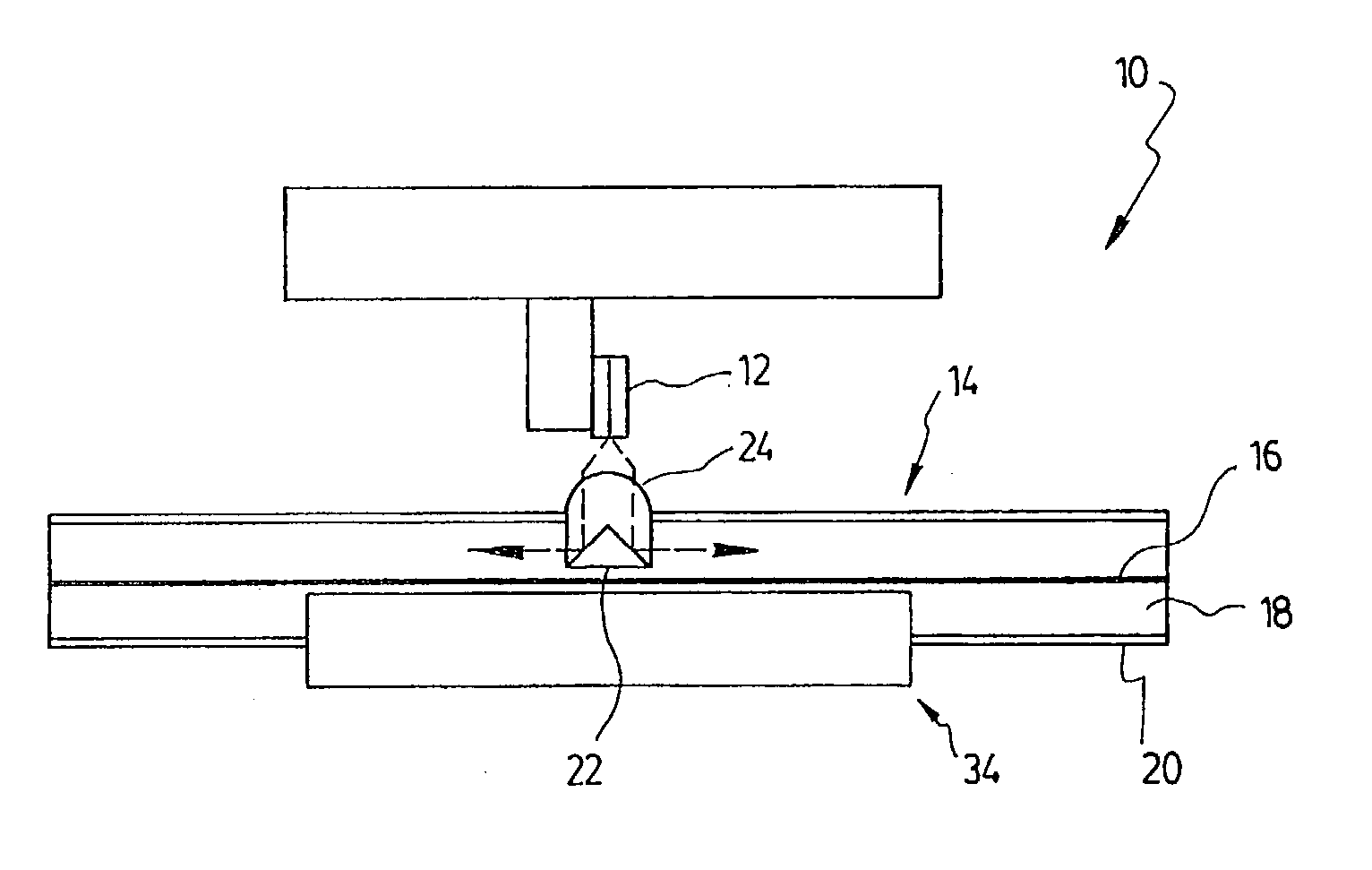
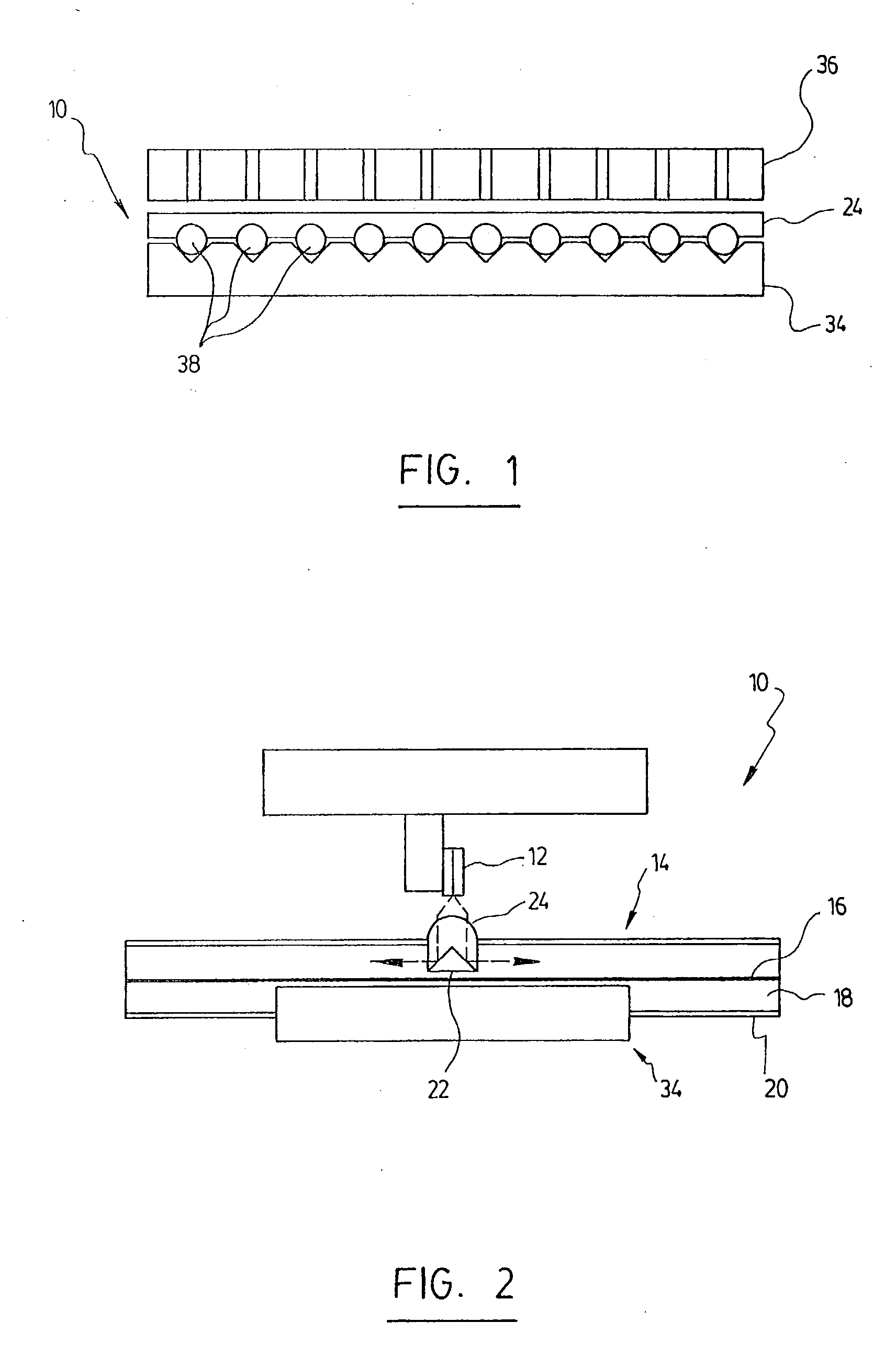
[0030] The general principle of the present invention is better illustrated in FIG. 2, showing a system 10 coupling light from a light source 12 into an optical fiber 14. In this case, the light source 12 is a laser diode part of a diode array, as will be explained in further details herein below. It is however understood that any other appropriate type of light source may be used.

[0031] The optical fiber is preferably a "double-core" (or "double-cladding") fiber, having an inner core 16 (preferably a mono-mode core which may be doped, for example in the case of a fiber amplifier)...


PUM


Abstract

A coupling technique for the side coupling of light from a light source into a waveguide is provided. A transversal groove is made into a section of the waveguide, extending into the target light guiding region. A coupling element is coupled to the light source at one of its end to receive the light beam therefrom. The opposite end of the coupling element is inserted in the groove and has at least one reflecting interface which specularly reflects the light beam for propagation into the waveguide. This technique may advantageously be used to couple light from the laser diodes of an array into one or a plurality of optical fibers.

Description

[0001] The present invention relates to the coupling of a light beam into an optical waveguide., More particularly, it concerns a device and method for the side-coupling of light from a light source into a waveguide, and is advantageously adapted to couple light from a laser diode array into one or a plurality of optical fibers.[0002] Launching of a light beam into a waveguide such as an optical fiber is one of the most basic challenges of any type of optical systems. One of the most common methods of optical coupling is the fiber pigtailing longitudinally launching a light beam into an optical fiber from one of its extremities. Fiber pigtailing however requires a precise alignment of all involved components, and most importantly, is limited to cases where a fiber extremity is available for such a coupling.[0003] To alleviate this latter drawback, several techniques for side coupling of a light beam into an optical fiber have been developed.[0004] For example, known in the art is U....

Claims


Application Information

Patent Timeline
IPC IPC(8): G02B6/42
CPCG02B6/4249G02B6/4214
Inventor DELADURANTAYE, PASCALCOURNOYER, ALAINTAILLON, YVESPETIT, STEPHANEDELADURANTAYE, MARC
Owner INSTITUT NATIONAL D'OPTIQUE
Learn More