
Apparatus and method for trace stream identification of multiple target processor events

Active Publication Date: 2004-07-08
TEXAS INSTR INC
View PDF4 Cites 21 Cited by
  • Summary
  • Abstract
  • Description
  • Claims
  • Application Information

AI Technical Summary

Problems solved by technology

However, the events in the host processor leading to the generation of event signals can be complicated.

Method used


Image

  • Apparatus and method for trace stream identification of multiple target processor events
  • Apparatus and method for trace stream identification of multiple target processor events
  • Apparatus and method for trace stream identification of multiple target processor events

Examples


Embodiment Construction

of the Figures

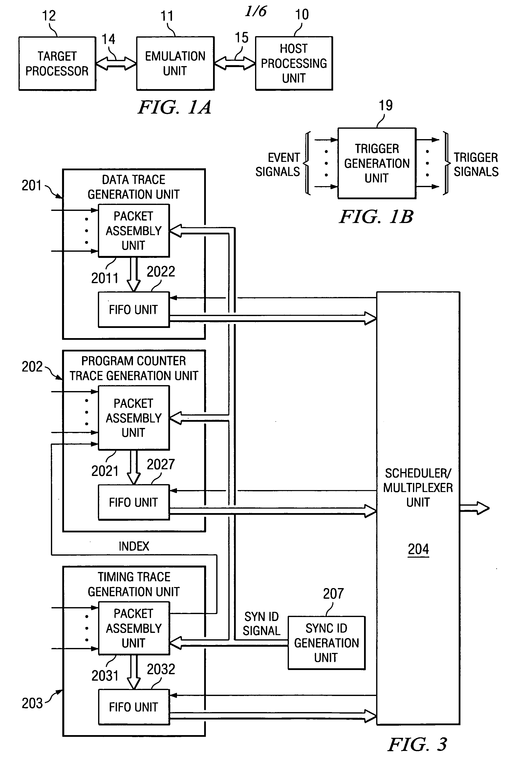
[0020] FIG. 1A and FIG. 1B have been described with respect to the related art.

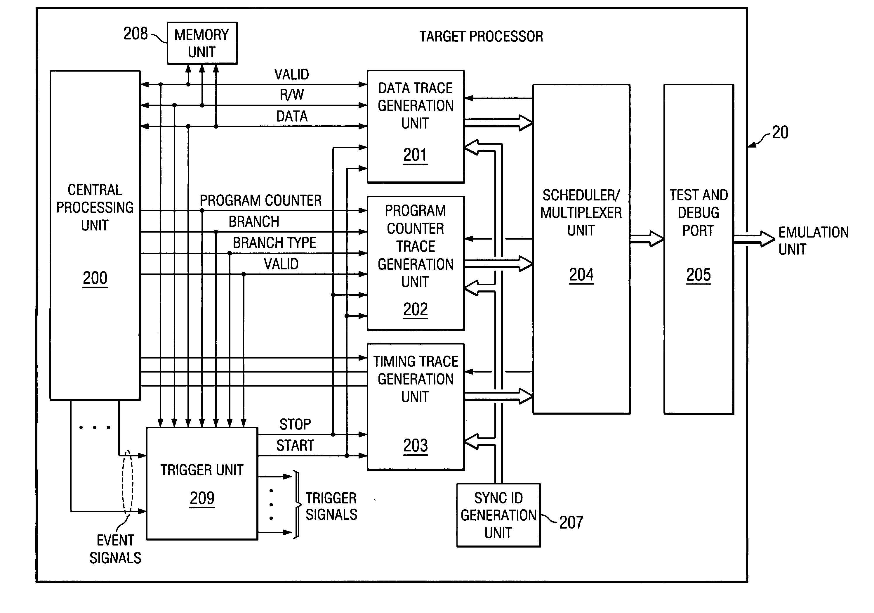
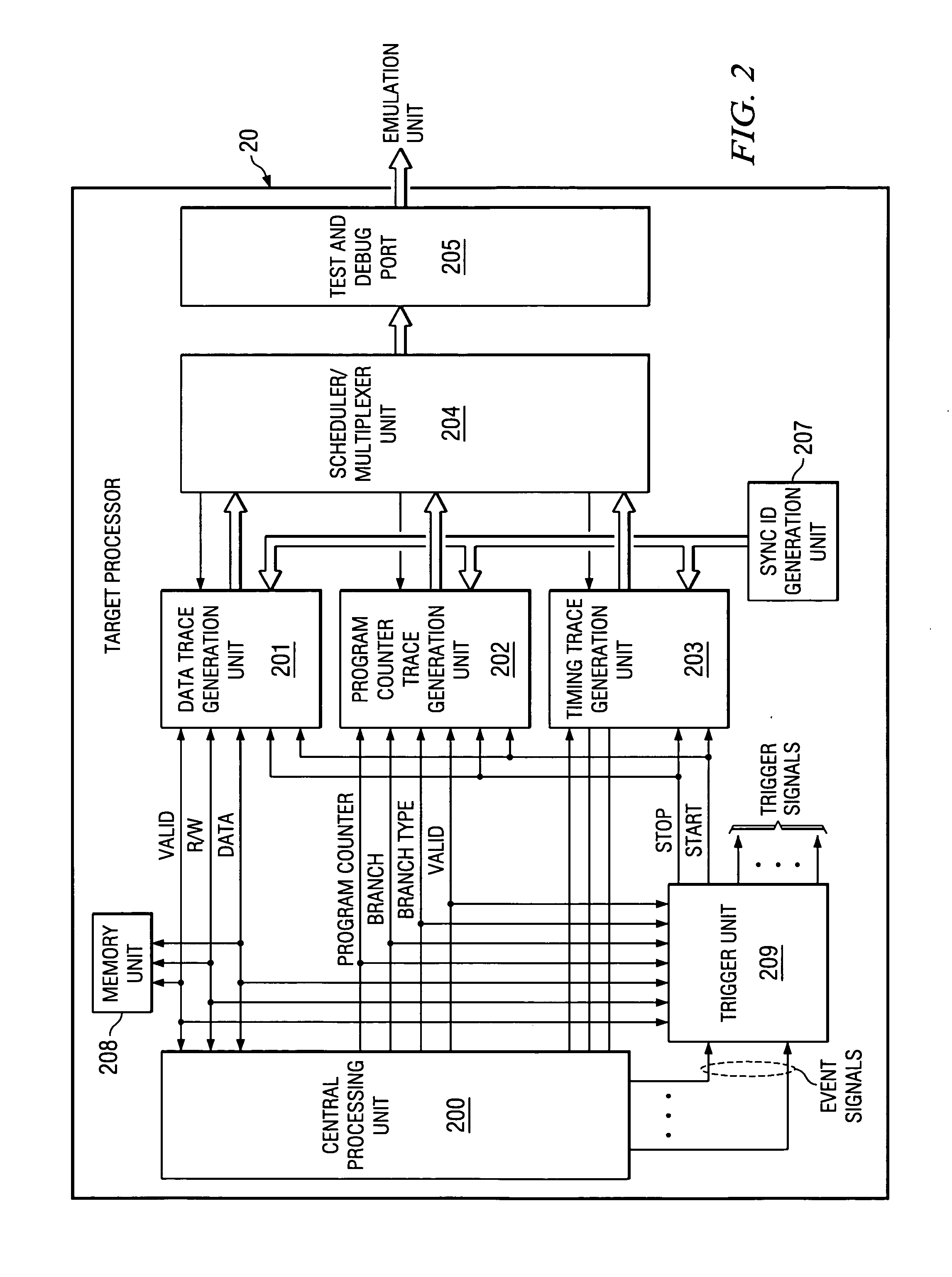
[0021] Referring to FIG. 2, a block diagram of selected components of a target processor 20, according to the present invention, is shown. The target processor includes at least one central processing unit 200 and a memory unit 208. The central processing unit 200 and the memory unit 208 are the components being tested. The trace system for testing the central processing unit 200 and the memory unit 202 includes three packet generating units, a data packet generation unit 201, a program counter packet generation unit 202 and a timing packet generation unit 203. The data packet generation unit 201 receives VALID signals, READ / WRITE signals and DATA signals from the central processing unit 200. After placing the signals in packets, the packets are applied to the scheduler / multiplexer unit 204 and forwarded to the test and debug port 205 for transfer to the emulation unit 11. The program counte...


PUM


Abstract

When a plurality of simultaneous, preselected target processor events are detected, a multiple-event sync marker is generated that identifies the preselected events and relates the occurrence of these events to timing trace stream. The sync marker for the plurality of preselected events differs from a single event sync marker by including at least one additional packet. The additional packet includes logic signals stored at locations related to each identified event.

Description

[0001] This application claims priority under 35 USC .sctn.119 (e) (1) of Provisional Application No. 60 / 434,174 (TI-34671P) filed Dec. 17, 2002.[0002] U.S. patent application (Attorney Docket No. TI-34654), entitled APPARATUS AND METHOD FOR SYNCHRONIZATION OF TRACE STREAMS FROM MULTIPLE PROCESSORS, invented by Gary L. Swoboda, filed on even date herewith, and assigned to the assignee of the present application; U.S. patent application (Attorney Docket No. TI-34655), entitled APPARATUS AND METHOD FOR SEPARATING DETECTION AND ASSERTION OF A TRIGGER EVENT, invented by Gary L. Swoboda, filed on even date herewith, and assigned to the assignee of the present application; U.S. patent application (Attorney Docket No. TI-34656), entitled APPARATUS AND METHOD FOR STATE SELECTABLE TRACE STREAM GENERATION, invented by Gary L. Swoboda, filed on even date herewith, and assigned to the assignee of the present application; U.S. patent application (Attorney Docket No. TI-34657), entitled APPARATUS...

Claims


Application Information

Patent Timeline
IPC IPC(8): H03K19/003
CPCG06F11/3636G06F11/3632
Inventor SWOBODA, GARY L.THOME, BRYAN
Owner TEXAS INSTR INC
Learn More