Fuel injection device for an internal combustion engine

a fuel injection device and internal combustion engine technology, applied in the direction of fuel injection apparatus, fuel feed system, spraying apparatus, etc., can solve the problems of inability to adjust the course of fuel injection in the desired way, and the fuel injection system is not optimal

Inactive Publication Date: 2004-04-08
ROBERT BOSCH GMBH
View PDF2 Cites 4 Cited by
  • Summary
  • Abstract
  • Description
  • Claims
  • Application Information

AI Technical Summary

Benefits of technology

[0003] The fuel injection system of the invention having the characteristics of claim 1 has the advantage over the prior art that when the second control valve has been opened for fuel injection and the fuel injection valve is thus open, only a small flow cross section from the control pressure chamber to the relief chamber is uncovered, and thus only a slight fuel quantity flows out; as a result, the pressure available for the injection and the efficiency of the fuel injection system are increased. At the onset of termination of fuel injection, fast opening and closure of the fuel injection valve are moreover attained, which is made possible by a fast pressure reduction and pressure buildup in the control pressure chamber upon opening and closure, respectively, of the second control valve, as a consequence of the variable flow cross section controlled by the control piston.[0004] Advantageous features and refinements of the fuel injection system of the invention are defined by the dependent claims. The embodiment of claim 2 makes it possible in a simple way to control the flow cross section.

Problems solved by technology

As a consequence, the efficiency of the fuel injection system is not optimal, and the course of the fuel injection cannot be adjusted in the desired way.

Method used


Image

  • Fuel injection device for an internal combustion engine
  • Fuel injection device for an internal combustion engine
  • Fuel injection device for an internal combustion engine

Examples


Embodiment Construction

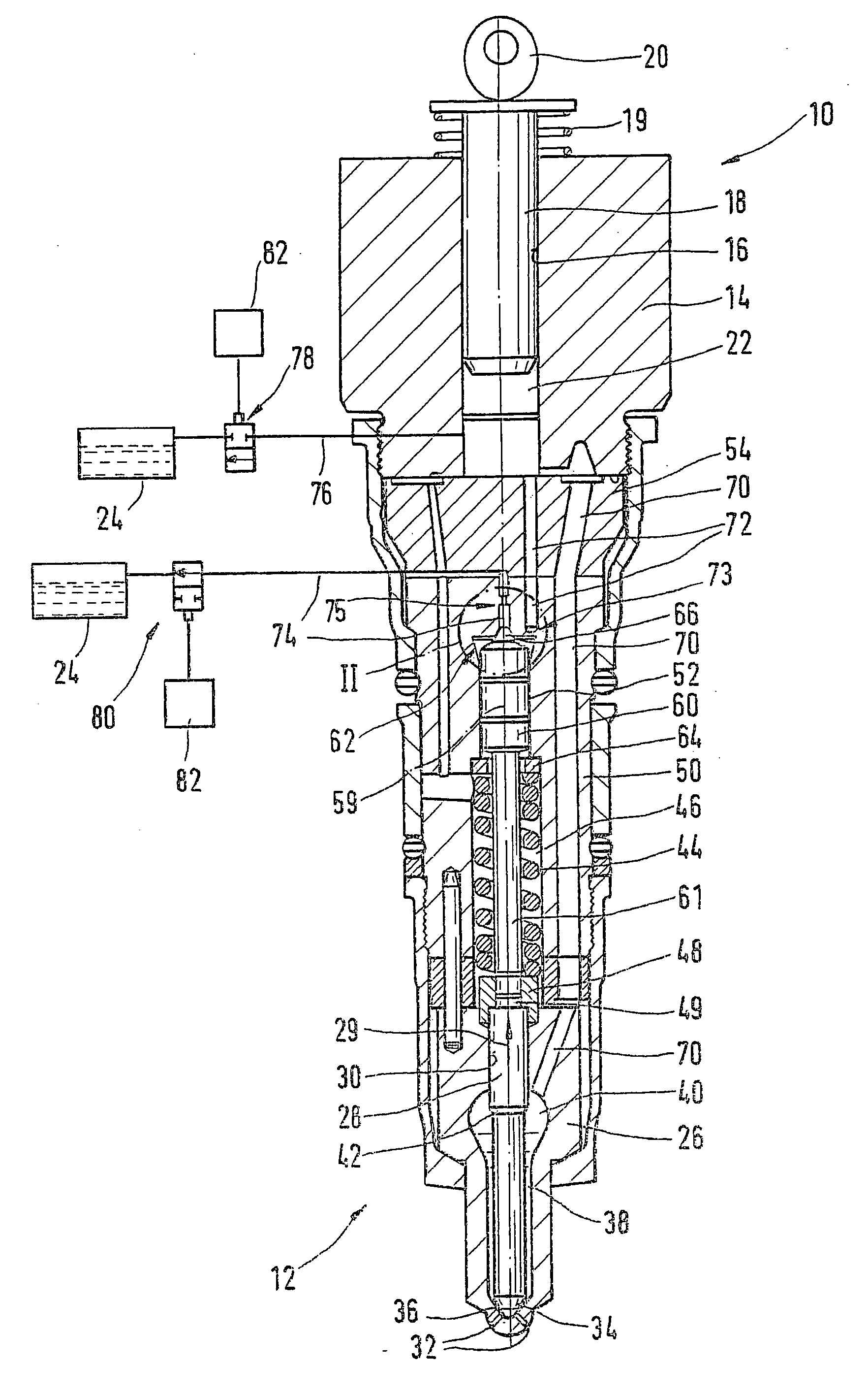
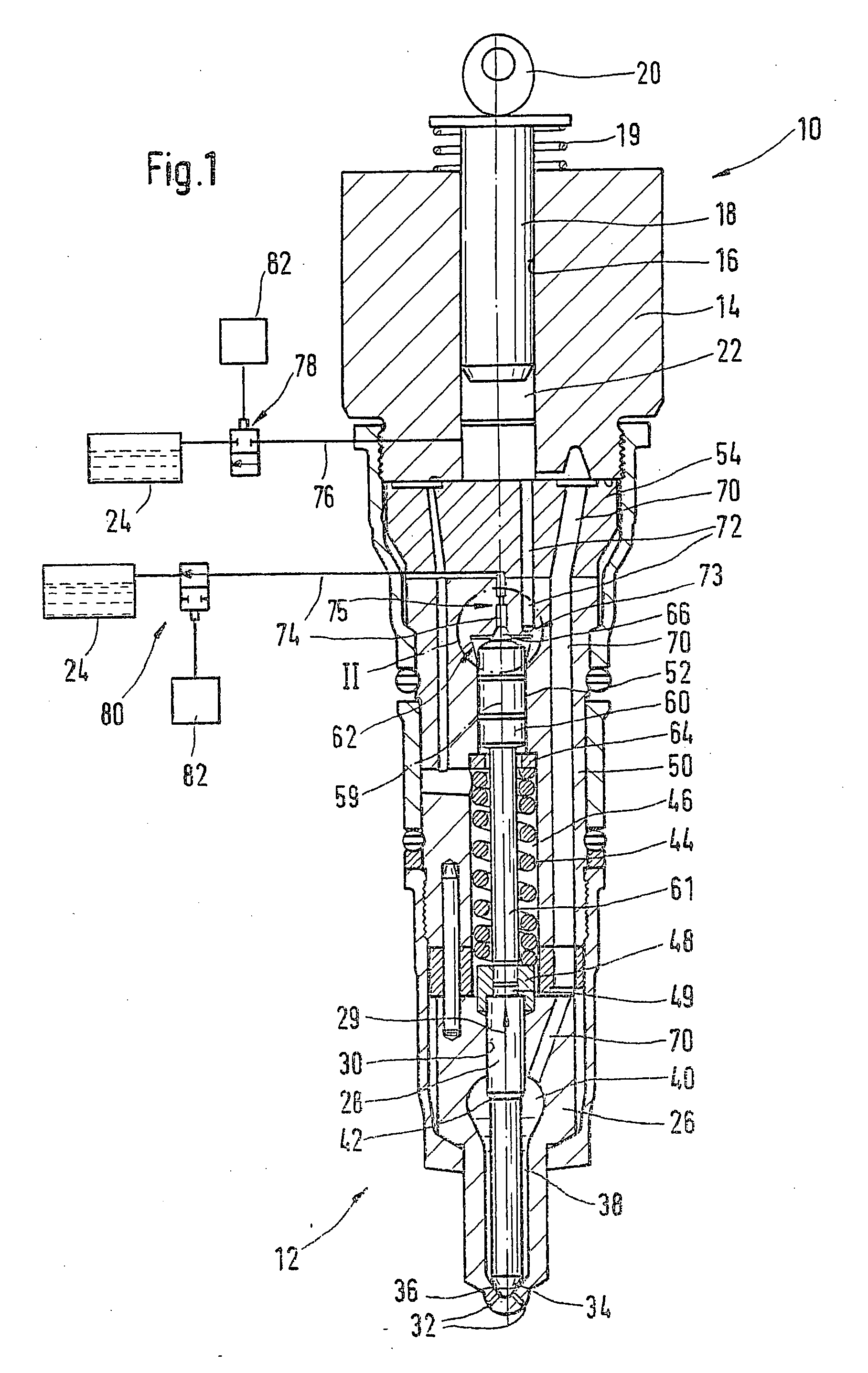
[0009] In FIGS. 1-3, a fuel injection system for an internal combustion engine of a motor vehicle is shown. The engine is preferably a self-igniting internal combustion engine. The fuel injection system is preferably embodied as a so-called unit fuel injector, and for each cylinder of the engine, it has one high-pressure fuel pump 10 and one fuel injection valve 12, communicating with it, and these form a common structural unit. Alternatively, the fuel injection system can be embodied as a so-called pump-line-nozzle system, in which the high-pressure fuel pump and the fuel injection valve of each cylinder are disposed separately from one another and communicate with one another via a line. The high-pressure fuel pump 10 has a pump body 14 with a cylinder bore 16, in which a pump piston 18 is guided tightly; the pump piston is driven in a reciprocating motion at least indirectly by a cam 20 of a camshaft of the engine, counter to the force of a restoring spring 19. In the cylinder bo...


PUM


Abstract

The fuel injection system has one high-pressure fuel pump (10) and one fuel injection valve (12), communicating with it, for each cylinder of the internal combustion engine. A pump piston (18) of the high-pressure fuel pump (10) defines a pump work chamber (22), which communicates with a pressure chamber (40) of the fuel injection valve (12); the fuel injection valve has an injection valve member (28), by which injection openings (32) are controlled and which is movable in an opening direction (29) counter to a closing force by the pressure prevailing in the pressure chamber (40). By means of a control valve (80), a connection (74) of the pump work chamber (22) with a relief chamber (24) is controlled, and having a second control valve (80), by which a connection (74) of a control pressure chamber (62), which communicates with the pump work chamber (22) and is defined by a control piston (60), with a relief chamber (24) is controlled, in which connection a throttle restriction (75) is provided. By means of the control piston (60), a flow cross section of the connection (74) of the control pressure chamber (62) with the relief chamber (24) is controlled as a function of the stroke of the control piston (60), such that with an increasing opening stroke of the injection valve member (28), a smaller flow cross section is uncovered by the control piston (60); and that at the maximum opening stroke of the injection valve member (28), the uncovered flow cross section is smaller than the flow cross section of the second throttle restriction (75).

Description

PRIOR ART[0001] The invention is based on a fuel injection system for an internal combustion engine as generically defined by the preamble to claim 1.[0002] One such fuel injection system is known from European Patent Disclosure EP 0 987 431 A2. This fuel injection system has one high-pressure fuel pump and one fuel injection valve communicating with it for each cylinder of the engine. The high-pressure fuel pump has a pump piston, which is driven by the engine in a reciprocating motion and defines a pump work chamber. The fuel injection valve has a pressure chamber communicating with the pump work chamber and also has an injection valve member, by which at least one injection opening is controlled and which is movable, acted upon by the pressure prevailing in the pressure chamber, in the opening direction counter to a closing force to uncover the at least one injection opening. A first electrically actuated control valve is provided, by which a connection of the pump work chamber w...

Claims


Application Information

Patent Timeline
Patent Type & Authority Applications(United States)
IPC IPC(8): F02M47/00F02M47/02F02M57/02F02M61/16
CPCF02M47/027F02M57/02F02M2200/28F02M2200/16F02M61/16
Inventor BOEHLAND, PETERKURRLE, MICHAELFISCHER, JOERG-PETER
Owner ROBERT BOSCH GMBH
Why Eureka
Try Eureka