
Process and device for modulating a carrier with amplitude and phase error compensation

a carrier and phase error compensation technology, applied in the field of rf carrier, can solve the problems of high cost, complex and expensive, and the limitation of phase and amplitude imbalances, and achieve the effect of reducing the cost of the method

Inactive Publication Date: 2004-03-11
THOMSON LICENSING SA
View PDF8 Cites 23 Cited by
  • Summary
  • Abstract
  • Description
  • Claims
  • Application Information

AI Technical Summary

Problems solved by technology

RF modulation is conventionally performed using a series of changes of frequency based on one or more local oscillators, this being complex and expensive.
It is however limited by the phase and amplitude imbalances engendered by the modulators, particularly at millimetre frequencies when using relatively big frequency bands.
These imbalances stem on the one hand from the static spread in hardware, and on the other hand from various drifting, in particular due to temperature.
This method has the drawback of being expensive.
To actually determine the errors it is necessary to send a calibrated signal from time to time, this having the drawback of then interrupting the transmission of the useful signal.
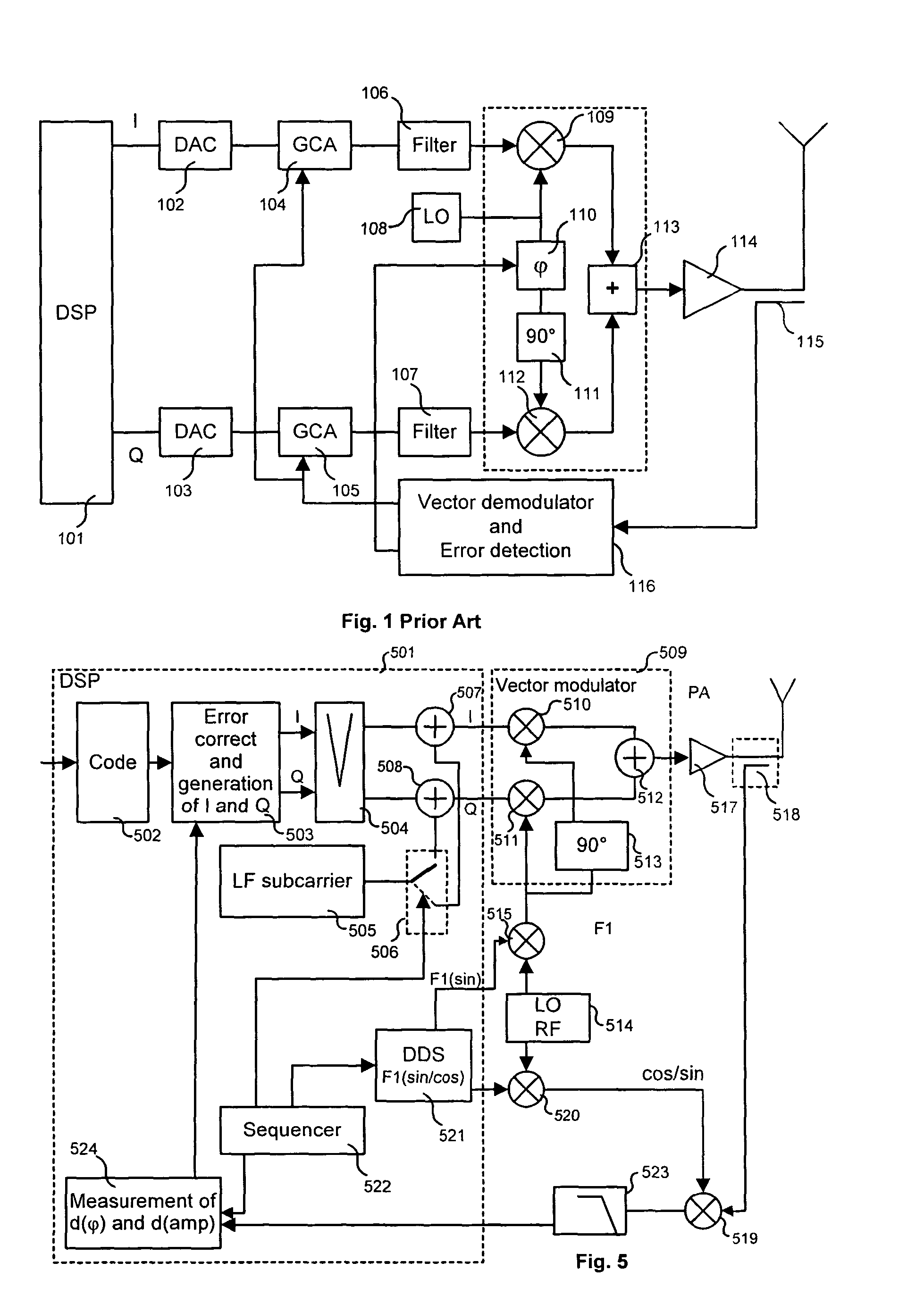
Furthermore, the vector demodulator 116 is itself marred by quadrature defects, thereby disturbing the correction.
Such an architecture is therefore not conceivable in these millimetre frequencies.

Method used


Image

  • Process and device for modulating a carrier with amplitude and phase error compensation
  • Process and device for modulating a carrier with amplitude and phase error compensation
  • Process and device for modulating a carrier with amplitude and phase error compensation

Examples


Embodiment Construction

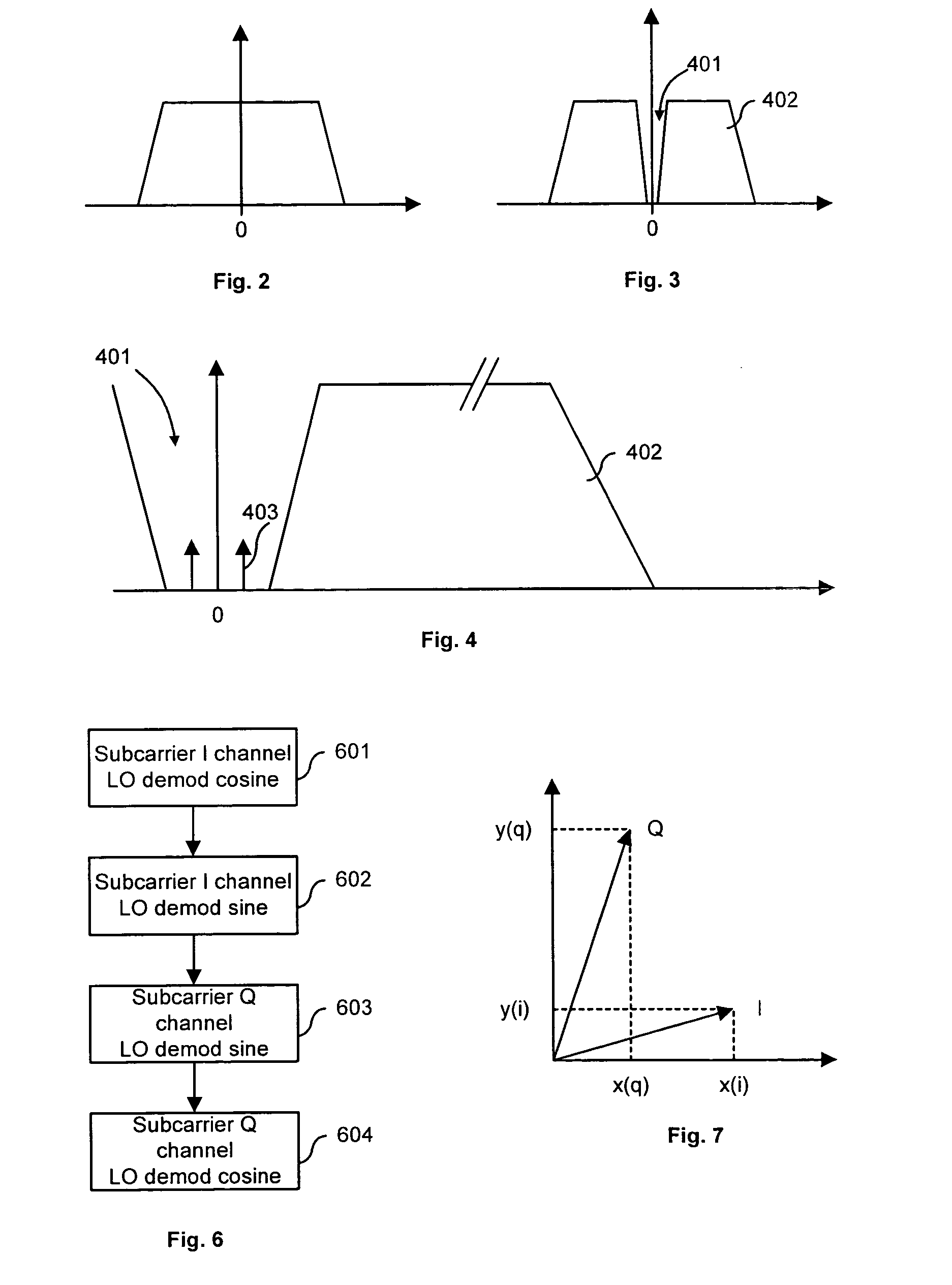
[0029] The baseband spectrum of the signals I and Q that are used in such a type of modulation is represented in a known manner in FIG. 2.

[0030] The process according to the invention proposes in a first step that part of this signal around the zero frequency be eliminated, as represented in FIG. 3.

[0031] This operation is carried out by digital filtering in the signal processor in the case of 4QAM type modulation, by way of example. By eliminating a very small frequency band compared with the useful band of the signal, the error made with regard to the useful signal then remains of second order.

[0032] In the case of the use of multicarrier type modulation, such as for example the OFDM (Orthogonal Frequency Division Multiplexing) type, it is quite simply sufficient to extinguish the carriers around 0, all of the useful signal located at this spot being carried over by coding into the other carriers.

[0033] As represented in FIG. 4, the invention next proposes that a subcarrier 403 be...


PUM


Abstract

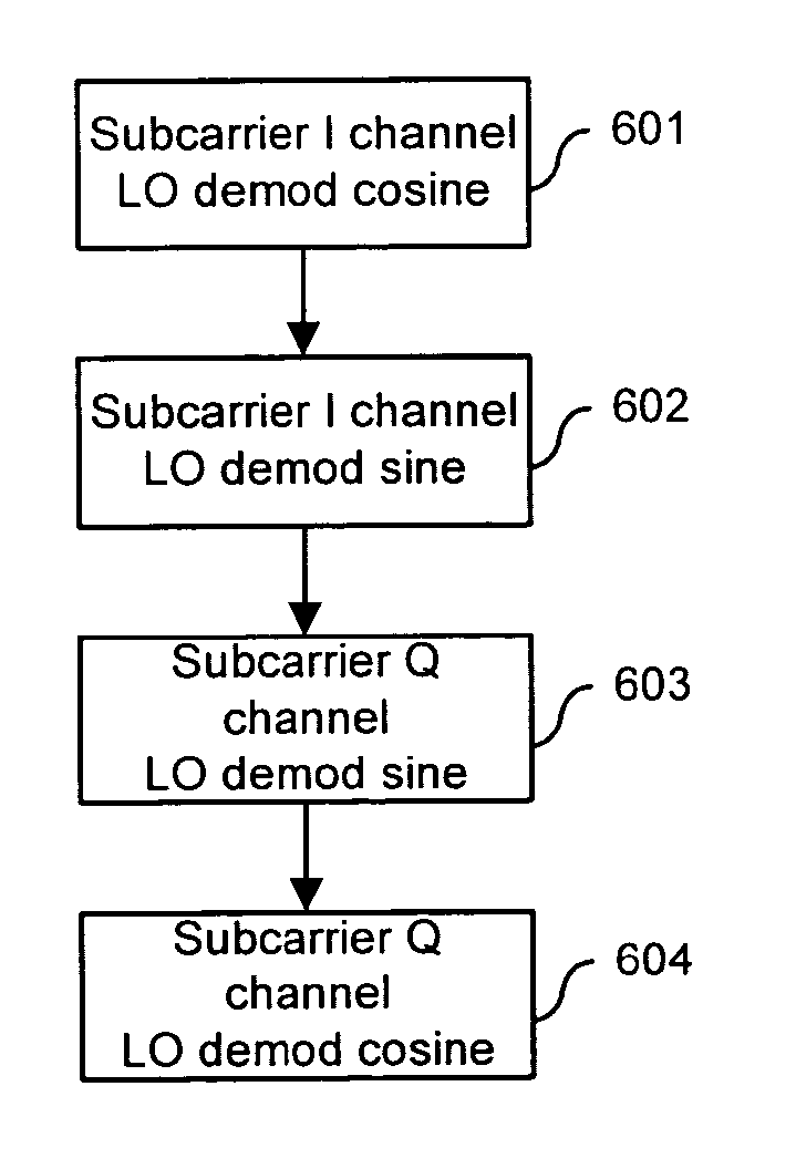
The invention relates to processes and devices which make it possible to directly modulate an RF carrier with a quadrature signal. It consists in filtering (504) this quadrature signal around zero so as to introduce alternately (507, 508) on each of the channels a low-frequency subcarrier that will serve as reference. Each of these channels is alternately demodulated in a synchronous manner (519) cosine-wise and sine-wise. The demodulation signal is filtered (523) so as to recover the subcarrier marred by modulation errors. The measurement of these errors (524) allows feedback correction (503) of the quadrature signal. It makes it possible to perform the major part of the operations in the digital processor (501) and enables direct vector modulation to be made possible at millimetre frequencies.

Description

[0001] 1. Field of the Invention[0002] The present invention concerns processes for modulating a carrier, more particularly an RF carrier, and in which the amplitude and phase errors engendered during this modulation are compensated for.[0003] It also relates to devices that make it possible to perform such modulation with such compensation. It applies mainly in satellite-based bidirectional multimedia communication systems, in particular those using the Ku band or the Ka band. It also relates to LMDS (standing for Local Multipoint Distribution System) type RF transmission systems.[0004] 2. Related Art[0005] RF modulation is conventionally performed using a series of changes of frequency based on one or more local oscillators, this being complex and expensive.[0006] It would be beneficial to dispense with these changes of frequency by performing direct vector modulation. This solution would be both simple and particularly inexpensive to effect. It is however limited by the phase and...

Claims


Application Information

Patent Timeline
Patent Type & Authority Applications(United States)
IPC IPC(8): H03C1/00H04L27/00H04L27/20H04L27/34H04L27/36
CPCH04L27/364H04L2027/0018H04L2027/0016H04L27/34
Inventor BARON, FRANCOISNAOUR, JEAN-YVES LEROBERT, JEAN-LUC
Owner THOMSON LICENSING SA
Learn More