Mass spectrometer and ion detector used therein

a mass spectrometer and ion detector technology, applied in the field of mass spectrometer and ion detector, can solve the problems of short life of continuous-dynode electron multiplier and inability to take accurate readings

Inactive Publication Date: 2004-03-04
HAMAMATSU PHOTONICS KK
View PDF6 Cites 17 Cited by
  • Summary
  • Abstract
  • Description
  • Claims
  • Application Information

AI Technical Summary

Problems solved by technology

Therefore, there is a range Y where the ion detector of U.S. Pat. No. 6,091,068 cannot take accurate readings.
Therefore, a large burden is placed on the secondary electron emissive surface in the channel so that the continuous-dynode electron multiplier has a short life.

Method used


Image

  • Mass spectrometer and ion detector used therein
  • Mass spectrometer and ion detector used therein
  • Mass spectrometer and ion detector used therein

Examples


Embodiment Construction

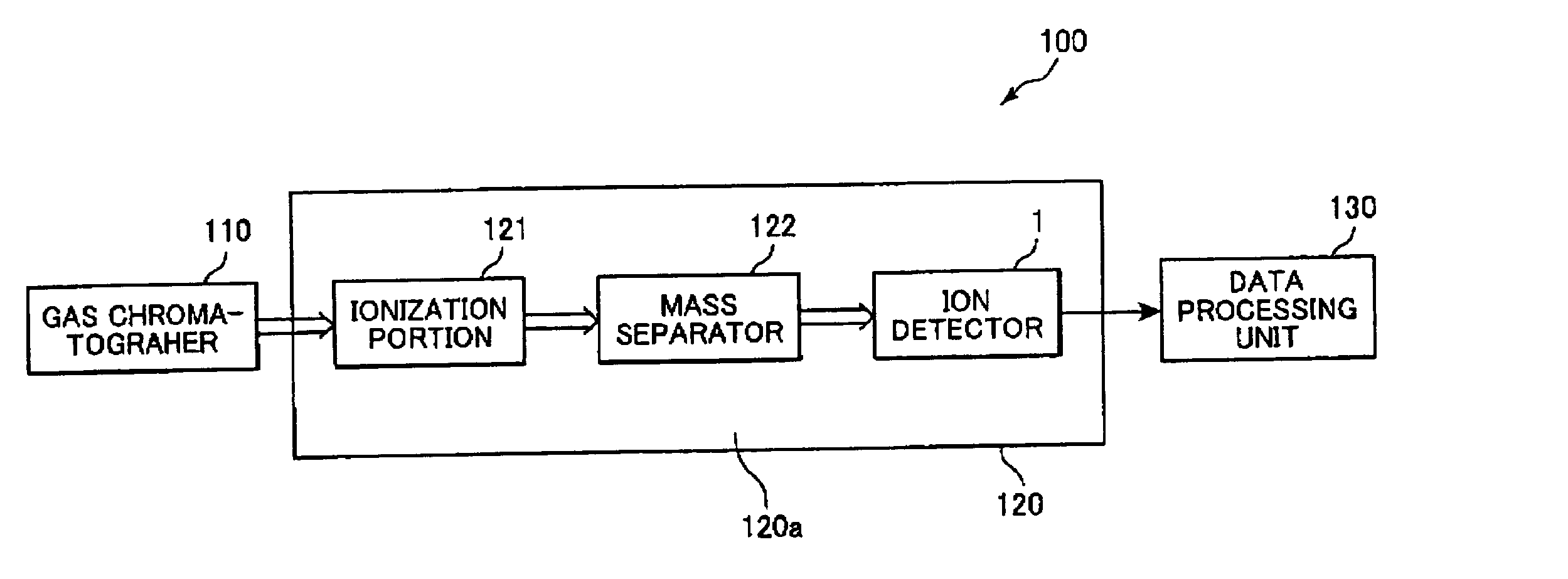
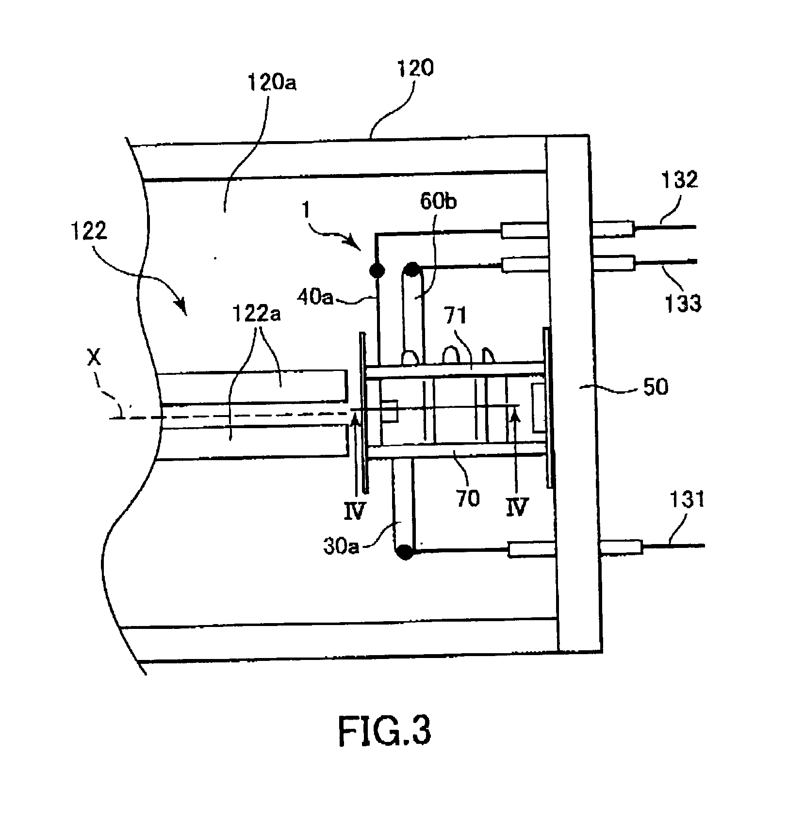
[0021] Next, a mass spectrometer 100 including an ion detector 1 according to an embodiment of the present invention will be described. As shown in FIG. 2, the mass spectrometer 100 includes a gas chromatographer 110, a stainless steel envelope 120, and a data processing unit 130. The gas chromatographer 110 includes a sampler injection port (not shown) through which liquid samples are injected. The envelope 120 houses an ionization portion 121, a mass separator 122, and the ion detector 1 within a vacuum chamber 120a. The ionization portion 121 includes a filament (not shown) for generating heat that converts molecules in the sample into positive or negative polarity ions. As shown in FIG. 3, the mass separator 122 includes cylindrical quadruple (Q-) pole electrodes 122a that are arranged in parallel around an imaginary axis X and that are electrically connected to the data processing unit 130. Four Q-pole electrodes 122a are provided, although only two are shown in the drawings.

[0...


PUM


Abstract

An ion detector includes an ion input face, a Faraday cup, an ion-to-electron converter dynode, two ion deflection electrodes, an electron multiplier portion, and an anode. The ion input face is formed with an ion input opening. The Faraday cup has an ion collection surface that confronts the ion input opening. The ion-to-electron converter dynode is disposed to one side with respect to the Faraday cup and the ion input opening and has a conversion surface that converts impinging ions into electrons. The two ion deflection electrodes generate an electron lens that attracts and focuses ions from the ion input opening toward the conversion surface of the ion-to-electron converter dynode. The electron multiplier portion receives and multiplies the electrons from the ion-to-electron converter dynode, and includes a plurality of dynodes that multiply electrons one after the other. The plurality of dynodes are juxtaposed in an arc-shape around the Faraday cup. The anode receives electrons from the electron multiplier portion and outputs a signal that corresponds to the amount of input ions.

Description

[0001] 1. Field of the Invention[0002] The present invention relates to a mass spectrometer and an ion detector used therein.[0003] 2. Description of the Related Art[0004] U.S. Pat. No. 6,091,068 discloses an ion detector that includes a Faraday cup and a tube-shaped continuous-dynode electron multiplier. (Details of a tube-shaped continuous-dynode electron multiplier are disclosed in U.S. Pat. No. 5,866,901.) In a Faraday cup mode of operation, the Faraday cup is connected to the input of an electrometer. The incoming ion beam formed from positively charged ions impinges on the collector plate of the Faraday cup. The ions are neutralized upon striking the collector plate, drawing a current as a signal output to the electrometer.[0005] The continuous-dynode electron multiplier in U.S. Pat. No. 6,091,068 includes a conical entrance opening. A grid shield is positioned adjacent to the conical entrance opening. During an electron multiplier mode of the ion detector, a high electrical p...

Claims


Application Information

Patent Timeline
Patent Type & Authority Applications(United States)
IPC IPC(8): H01J49/02
CPCH01J49/025
Inventor YAMAGUCHI, HARUHISANAKAMURA, MAKOTOOKAMOTO, TAKEHISASUZUKI, HIROSHIOHMURA, TAKAYUKI
Owner HAMAMATSU PHOTONICS KK
Why Eureka
Try Eureka