
Device for radiation therapy

a radiation therapy and device technology, applied in the field of radiation therapy, can solve the problems of reducing the sterilization efficiency of the device,

Inactive Publication Date: 2004-01-22
KUMAKHOV MURADIN ABUBEKIROVICH
View PDF6 Cites 4 Cited by
  • Summary
  • Abstract
  • Description
  • Claims
  • Application Information

AI Technical Summary

Benefits of technology

[0012] easy transformation by the way of probe replacement, in particular, for changes of its size, and changes in energy and directional radiation pattern acting on the pathological locus;
[0013] simplicity of the probe sterilization, and possibility of utilization of interchangeable or disposable probes;
[0018] Due to the absence of vacuum and high electric voltage in the probe it may be executed as a removable one, thus making easy its sterilization. The device may be provided with a set of probes having different size.

Problems solved by technology

This method has drawbacks of the necessity of surgical intervention and associated with it difficulty in the control of irradiation duration.
This fact in combination with the necessity of high voltage supply to the anode situated at distal end of a thin lengthy probe and the necessity to control position of electronic beam make for design complexity of the device.
Impossibility of anode replacement in the evacuated probe results in necessity of having separate device for each radiation energy desired.
Realization of the probe as a part of X-ray tube complicates substantially its sterilization.
Overcoming of this drawback by providing the probe with removable sheath increases its diameter and is associated with a rise in traumatism on utilization of the device.

Method used


Image

  • Device for radiation therapy
  • Device for radiation therapy
  • Device for radiation therapy

Examples


Embodiment Construction

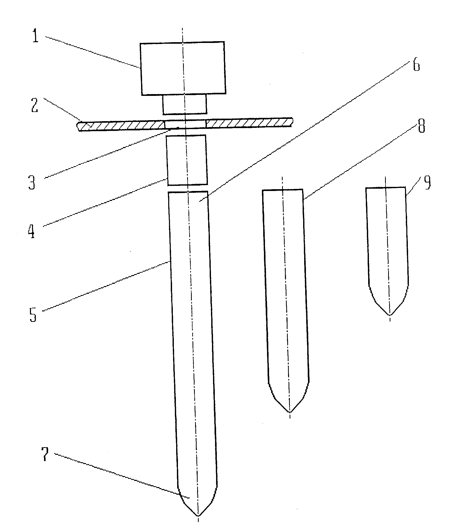
[0041] The device proposed comprises (FIG. 1, A) a source of neutral particles (X-ray or gamma quanta or neutrons), protective shield 2 with a diaphragm 3 situated in front of the outlet aperture of source 1, means 4 of formation of particle beam oriented along longitudinal axis of the probe 5. The latter has tapered distal end 7. Proximal end 6 of the probe 5 may be executed in such a way as to ensure possibility of the probe removal (for example, for sterilization and replacement with another one). The set of the device may include several probes, for example, of different length (FIGS. 1, B and C).

[0042] The probe may be similar in form and dimensions to a puncture needle for biopsy.

[0043] In the course of device usage the probe is introduced, depending on the localization of pathological locus, into one of the natural passages of patient's body or perform puncturing similar to biopsy procedure.

[0044] FIG. 2 shows position of the probe 5 in the body of patient 11. Quasi-parallel ...


PUM


Abstract

Device, related to the means for radiation therapy of malignant and benign neoplasms and certain other diseases, comprise hollow probe 5, source 1 of neutral particle radiation in the form of X-ray or gamma quanta or neutrons, and means of shaping the particle beam of said radiation oriented by the longitudinal axis of the probe. Means of shaping the particle beam is executed in the form of collimator or lens 18 comprising aggregate of curved channels for radiation transmission with a total internal reflection. Said means may be located inside of the probe 5. On using the device, probe 5 is introduced into the body of patient 11, with its distal end 7 approaching pathological locus 13 or inserted directly into it. For exposure of pathological locus, use is made of radiation of the neutral particles source directly or secondary radiation excited in the target placed in the distal end of the probe or radiation dissipated with this target. Design of the device requires no evacuation of the probe and use of high voltage in the latter, is easily transformed by the probe replacement, in particular, to change its size, to change energy and directional pattern of radiation affecting the pathological locus. Making of the probe removable simplifies its sterilization. 1 independent claim and 42 dependent claims, 10 figures of drawings.

Description

Field of the Invention[0001] The present invention relates to means for radiation therapy of malignant and benign neoplasms and certain other diseases.Background of the Invention[0002] At present, treatment with ionizing radiation is widely used not only in the therapy of malignant neoplasms, but benign tumors and a series of inflammatory and other diseases of nonneoplastic nature as well (Aspects of Clinical Dosimetry, Ed. R. V.Stavitskij, Moscow, "MNPI", 2000 [1] (in Russian)).[0003] Devices are known for radiation therapy which comprise X-ray source, oriented for the purpose of directing radiation created with it to the pathological locus area. In order to minimize irradiation of healthy tissues surrounding pathological locus, such devices may comprise several X-ray sources. The irradiation created with them is directed to the pathological locus area from different directions (Radiation Therapy of Malignant Tumors. Guide for Physicians. Ed. Prof. E. S.Kiseleva, Moscow, "Meditsina...

Claims


Application Information

Patent Timeline
IPC IPC(8): A61N5/10G21K1/06G21K5/02
CPCA61N5/1001A61N5/1014G21K2201/067G21K2201/064G21K1/06A61N2005/1091A61N2005/1095
Inventor KUMAKHOV, MURADIN ABUBEKIROVICH
Owner KUMAKHOV MURADIN ABUBEKIROVICH
Learn More