Current control device

Inactive Publication Date: 2004-01-22
QORTEK
View PDF4 Cites 2 Cited by
  • Summary
  • Abstract
  • Description
  • Claims
  • Application Information

AI Technical Summary

Problems solved by technology

Such devices are neither gap-less nor shock resistant, therefore prone to chatter and subject to arcing.
Chatter and arcing pose substantial problems in many high-voltage applications.
However, PCL composites are conductive when compressed and interrupt current flow by polymer decomposition.
During a fault, temperature within the composite increases causing limited decomposition and evolution of gaseous products.
Furthermore, static compression of the composites increases time-to-interrupt by damping gap formation.
Neither PTCR nor PCL applications provide for the dynamically-tunable compression of a composite in response to electrical load conditions.
However, piezoresistive compositions resist compression.
Temperature dependent interrupt is slowed by the poor thermal conduction properties of the polymer matrix.
Furthermore, decomposition limits the life cycle of a composition.

Method used


Image

  • Current control device
  • Current control device
  • Current control device

Examples


Embodiment Construction

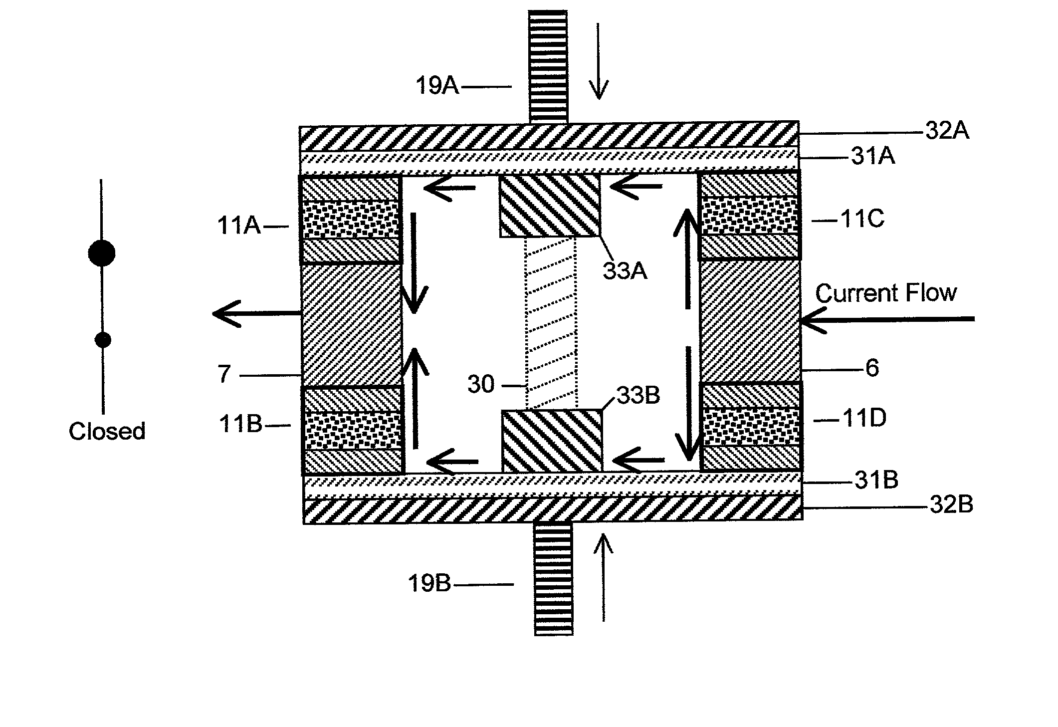
[0070] Two embodiments of the present invention are comprised of a rectangular solid composite 4 contacting and sandwiched between two or more plates, namely a planar first electrode 6 and a planar second electrode 7, as shown in FIG. 3, and a planar first electrode 6 and a planar second electrode 7 and two planar pressure plates 18a, 18b, as shown in FIG. 4. A pressure switch 11 is comprised of a composite 4 and electrodes 6, 7 as shown in FIG. 3 or a composite 4 and pressure plates 18a, 18b as shown in FIG. 4.

[0071] The composite 4 functionally completes the current path between first electrode 6 and second electrode 7 during acceptable operating conditions and interrupts current flow when a fault condition occurs. The composite 4 is either conductive or resistive based on the pressure state within the composite 4. For example, the composite 4 may be conductive above and nonconductive below a threshold pressure. Alternately, the resistivity of the composite 4 may vary with pressur...


PUM

PropertyMeasurementUnit
Temperatureaaaaaaaaaa
Forceaaaaaaaaaa
Pressureaaaaaaaaaa

Abstract

A current control device is described wherein a pressure conduction composite is compressed and decompressed to alter its conductivity and thereby current conduction through the device. The pressure conduction composite is composed of a nonconductive matrix, a conductive filler, and an additive. The invention consists of electrodes, a nonconducting isolator, and pressure plates contacting the composite. Electrically activated actuators apply a force onto pressures plates. Actuators are composed of a piezoelectric, piezoceramic, electrostrictive, magnetostrictive, and shape memory alloy materials, capable of extending and / or contracting thereby altering pressure and consequently resistivity within the composite. In an alternate embodiment, two or more current control devices are electrically coupled parallel to increase power handling.

Description

[0001] The application claims benefit under 35 U.S.C. 119(e) from U.S. Provisional Application No. 60 / 267,306 filed on Feb. 8, 2001.[0003] 1. Field of the Invention[0004] The present invention generally relates to a current control device for regulating current flow. The invention specifically described is a device wherein current flow is regulated by compression and expansion of a composite.[0005] 2. Related Arts[0006] Mechanical circuit breakers are best described as a switch wherein a contact alters the electrical impedance between a source and a load. Mechanical breakers are typically composed of a snap-action bimetal-contact assembly, a mechanical latch / spring assembly, or an expansion wire. Such devices are neither gap-less nor shock resistant, therefore prone to chatter and subject to arcing. Chatter and arcing pose substantial problems in many high-voltage applications.[0007] Variably conductive composites are applicable to current control devices. Compositions include posit...

Claims


Application Information

Patent Timeline
IPC IPC(8): H01C7/02H01C10/10
CPCH01C7/027H01C7/13H01C10/103H01C10/106H01C17/06586Y10T29/49105Y10T29/49128Y10T29/49147Y10T29/435Y10T29/4902Y10T29/49082Y10T29/49098
Inventor BOWER, BRUCEKNOWLES, GARETH
Owner QORTEK
Why Eureka
Try Eureka