
Quality of displayed images with user preference information

a technology of user preference and displayed images, applied in the field of increasing the perceived quality of displayed images, can solve the problems of affecting the perceived quality of lcd displays, flat panel displays tend to be small and lightweight, and older computer crt display devices are more difficult to read than new crts

Inactive Publication Date: 2004-01-15
MICROSOFT TECH LICENSING LLC
View PDF46 Cites 151 Cited by
  • Summary
  • Abstract
  • Description
  • Claims
  • Application Information

AI Technical Summary

Benefits of technology

[0017] Using information relating to a specific user's viewing preferences and / or ability to perceive image characteristics such as color also improves the perceived quality of displayed images. By customizing display output to an individual user's own physical perception; capabilities and / or viewing characteristics it is possible to enhance the image quality perceived by the individual viewer as compared to embodiments which do not take into consideration individual user characteristics.
[0021] Ambient light conditions are measured, in accordance with one feature of the present invention, using the same device used to periodically measure display device light output characteristics. The ambient light condition information may include, e.g., information on whether a room light is on or off and / or information on the color components of the ambient light present. Ambient light condition information is used in an exemplary embodiment when controlling the display's light output. For example, information that the ambient light includes relatively more blue than red or green light, e.g., due to the use of fluorescent lights, results in a controlled decrease in the relative intensity of blue light emitted by the display device.
[0023] The above discussed methods of improving the perceived quality of displayed images can be used individually or in combination. While the methods and apparatus of the present invention can be used to enhance the perceived image quality of most display devices, they are well suited for use with color flat panel display devices, e.g., LCD displays. In order to enhance the image quality of color LCD display devices, e.g., when rendering text, the luminous intensity of pixel sub-components can be independently controlled so that each pixel sub-component can be used to represent different portions of an image. While this technique of pixel sub-component control can provide a gain in effective resolution in one dimension, it can lead to color distortions which can be caused by the independent luminous intensity control of pixel sub-components. In such systems, color correction processing may be used to detect and reduce or eliminate what would be interpreted by most people as objectionable color distortions. Unfortunately, such color correction or compensation operations tend to reduce the benefit in terms of increased effective resolution that is provided by treating the different color pixel sub-components as independent luminance sources.

Problems solved by technology

Thus, older computer CRT display devices tend to be more difficult to read than new CRTs.
This is because flat panel displays tend to be small and lightweight in comparison to CRT displays.
While LCD devices offer some advantages over CRT display devices in terms of power consumption and weight, the perceived quality of LCD displays can be significantly impacted by viewing angle.
While this technique of pixel sub-component control can provide a gain in effective resolution in one dimension, it can lead to color distortions which can be caused by the independent luminous intensity control of pixel sub-components.
Unfortunately, such color correction or compensation operations tend to reduce the benefit in terms of increased effective resolution that is provided by treating the different color pixel sub-components as independent luminance sources.
With color compensation disabled normally objectionable color distortions may exist in the displayed images.

Method used


Image

  • Quality of displayed images with user preference information
  • Quality of displayed images with user preference information
  • Quality of displayed images with user preference information

Examples


Embodiment Construction

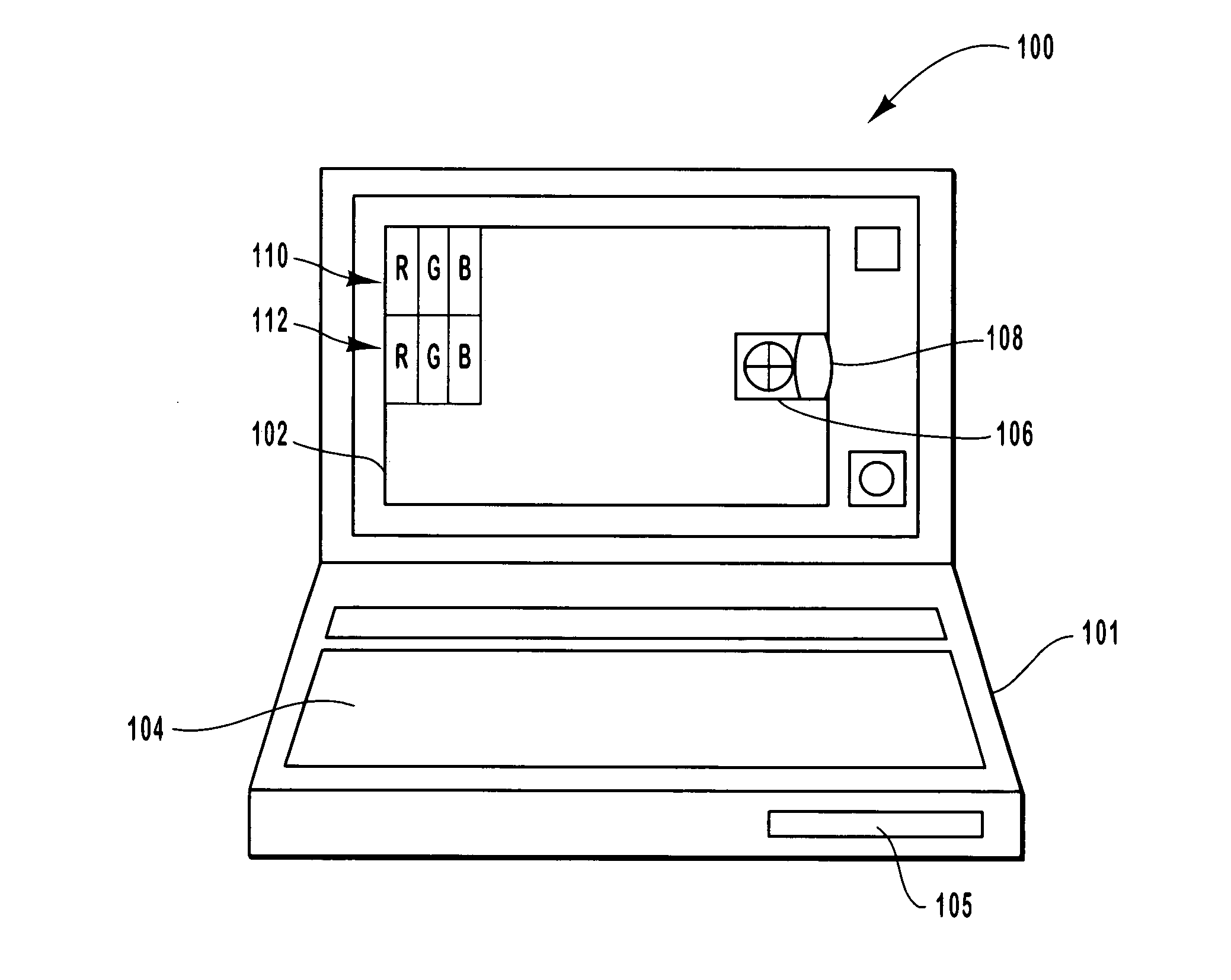
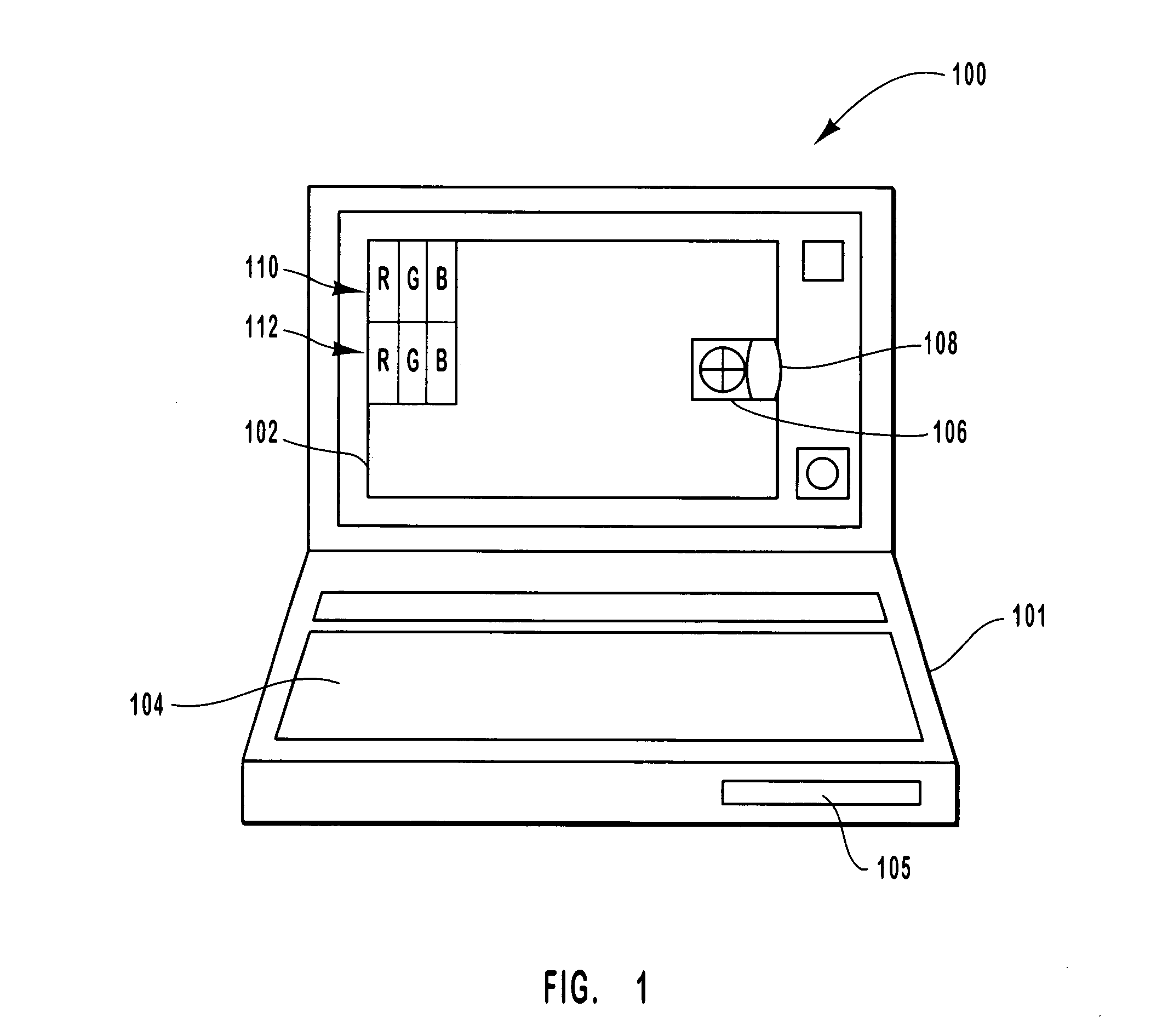
[0045] FIG. 1 illustrates a portable computer system 100, which comprises a housing 101, a disk drive 105, keyboard 104 and a flat panel display 102. The display 102 is implemented as an LCD display device with vertical RGB striping. Each set of R, G, B pixel sub-components 110, 112 represent one pixel. While only two pixels 110, 112 are shown, it is to be understood that the display 102 comprises many rows and columns of such pixels. The computer system 100 includes a light measuring device 106 which is mounted using a hinge 108. The sensor 106 can be positioned in front of the display 102, as shown in FIG. 1, to measure the actual light output of the display 102. Such measurements may be taken periodically, in accordance with the present invention, when data on the state of the display device 102 is to be measured and used for updating a display profile. During the measurement, a pre-selected test pattern may be displayed on the screen 102.

[0046] When not being used to measure scr...


PUM


Abstract

The present invention relates to methods and apparatus for increasing the perceived quality of displayed images. This is achieved in a variety of ways including the use of a plurality of device specific display characteristics when preparing images for display. It is also achieved through the monitoring of display device and / or ambient light conditions, e.g., on a periodic basis, and using the obtained information when controlling display output. Another approach to improving the perceived quality of displayed images involves the use of information relating to a specific user's ability to perceive image characteristics such as color. By customizing display output to an individual user's own physical perception capabilities and / or viewing characteristics it is possible to enhance the image quality perceived by the individual viewer as compared to embodiments which do not take into consideration individual user characteristics.

Description

[0001] This application is a continuation of U.S. patent application Ser. No. 09 / 364,648, filed Jul. 30, 1999, which claims the benefit of U.S. Provisional Patent Application Serial No. 60 / 118,087 filed Feb. 1, 1999. The foregoing patent applications are incorporated herein by reference.[0002] 1. Field of the Invention[0003] The present invention relates to methods and apparatus for displaying images, and more particularly, to methods and apparatus for increasing the perceived quality of displayed images.[0004] 2. Background of the Invention[0005] Color display devices have become the principal display devices of choice for most computer users. The display of color on a monitor is normally achieved by operating the display device to emit light, e.g., a combination of red, green, and blue light, which results in one or more colors being perceived by a human viewer.[0006] In cathode ray tube (CRT) display devices, the different colors of light are generated via the use of phosphor coa...

Claims


Application Information

Patent Timeline
IPC IPC(8): G06F1/16G09G3/20G09G5/00G09G5/02
CPCG06F1/1607G09G2360/144G09G5/005G09G5/006G09G5/02G09G2320/02G09G2320/028G09G2320/06G09G2320/0606G09G2320/0626G09G2320/0666G09G2320/0673G09G2320/0693G09G2340/0407G09G2340/0457G09G5/00
Inventor DRESEVIC, BODINHILL, WILLIAMHITCHCOCK, GREGORYKEELY, LEROY B.PLATT, JOHN C.WHITTED, J. TURNER
Owner MICROSOFT TECH LICENSING LLC
Learn More