
Audio signal system

a signal system and audio technology, applied in the field of audio signal devices, can solve the problems of not being able to use in-the-ear and in-the-canal, the bulky and cumbersome use of the system, and the inability of the majority of users to provide the quality audio sound required, so as to enhance the perceived quality of the audio signal and improve the quality of the perceived audio signal

Inactive Publication Date: 2006-02-09
ABLE PLANET
View PDF15 Cites 37 Cited by
  • Summary
  • Abstract
  • Description
  • Claims
  • Application Information

AI Technical Summary

Benefits of technology

[0007] The audio signal system herein disclosed advances the art and overcomes problems articulated above by providing a system for modifying an audio signal projected toward a receiver, wherein the modification improves the perceived quality of the audio signal.
[0011] In still yet another embodiment, provided is an improved audio signal system of the type in which an electrical signal, derived from a received audio signal, is used by an output device to replicate the received audio signal, wherein the improvement includes a modifying mechanism for modifying the characteristics of the replicated audio signal to improve perceived replicated audio signal quality.
[0012] In one embodiment, provided is an audio signal system including: an output means for outputting an audio signal; a means for inducing a magnetostrictive core to vibrate; and a means for coupling a vibratory output of the magnetostrictive core with an audio signal from the outputting means to enhance the perceived quality of the audio signal.

Problems solved by technology

Size restrictions and functional limitations prevent current telephone-hearing aid couplers from providing the quality audio sound required / desired by the hearing impaired.
Some systems are bulky and cumbersome to use, and most cannot be used with in-the ear and in-the-canal (“ITC”) type hearing aids.
Additionally, many prior art devices operate in a set, and very limited frequency range, effectively eliminating the ability of a hearing impaired person to hear sounds across a broad range of frequencies.

Method used


Image

  • Audio signal system
  • Audio signal system
  • Audio signal system

Examples


Embodiment Construction

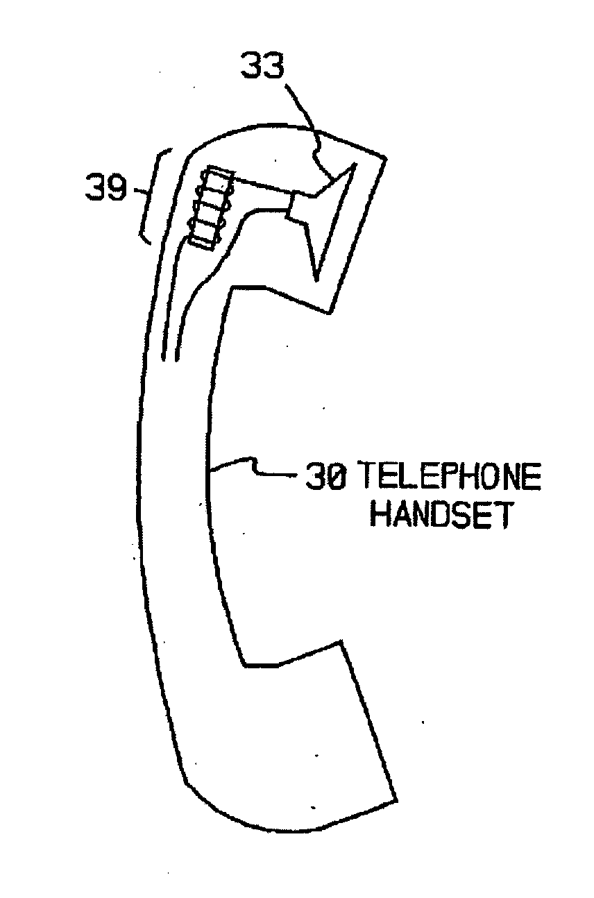
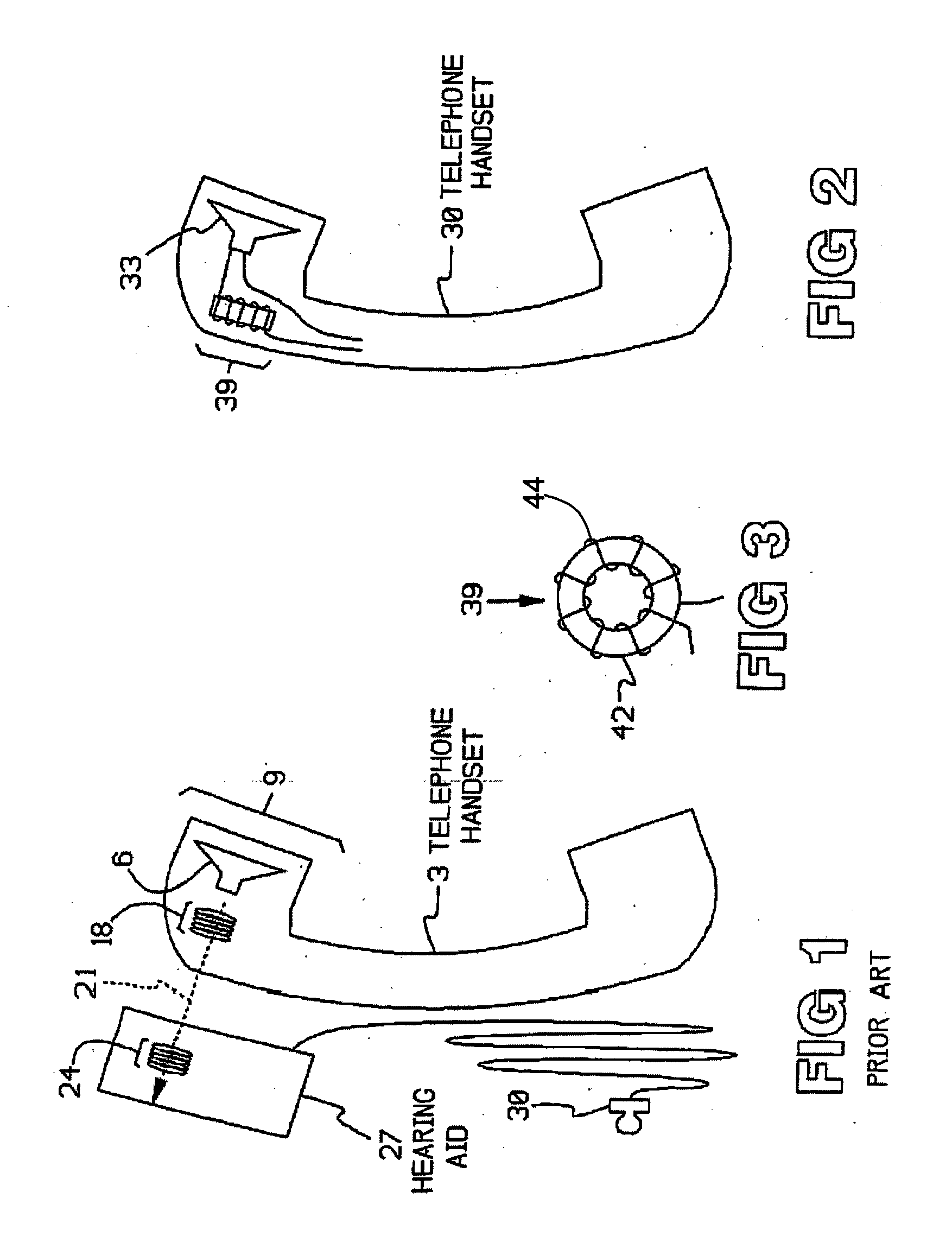
[0026]FIG. 1 illustrates a telephone handset 3, which contains a loudspeaker 6 in the earpiece 9. Many such handsets are equipped with an HAC coil 18, which can be connected with the speaker 6. Such coil-equipped handsets are often termed type-HAC, or Hearing Aid Compatible. The HAC coil 18 produces a magnetic field 21, which couples with a similar coil 24, often termed a T-coil, or telephone coil, within a nearby hearing aid 27, when the latter is held near the handset 3.

[0027] The coupling between HAC coil 18 and coil 24 transfers an electromagnetic field derivative of an electronic signal received by the speaker 6 to the hearing aid 27, wherein hearing aid 27 transforms the field back into an electronic signal. The electromagnetic coupling thus allows the hearing aid to receive substantially the same electronic signal received by the speaker 6. The hearing aid 27 then delivers the signal to an earpiece 30, or other device, wherein the signal is converted to an audio signal (e.g....


PUM


Abstract

An audio signal system is provided having, in one embodiment, a magnetostrictive core of varying shapes, sizes, and permeability. The core is wound with a wire, thereby forming an inductor for producing a magnetic field when current is passed through the wire. A speaker, or other audio output device, is positioned in parallel or series with the inductor. In operation, an audio signal is received and transmitted to the speaker or other audio output device, wherein a replication of the received signal is produced. An output of the magnetostrictive inductor couples with the replicated audio signal to modify and enhance the quality of the projected signal. In yet another embodiment, digital signal processing may be used to modify the received signal as well.

Description

RELATED APPLICATION [0001] This application is a continuation-in-part of previously filed U.S. patent application Ser. No. 10 / 864,692, “Improved Telephone Handset”, filed Jun. 9, 2004; this application is also continuation-in-part of previously filed U.S. patent application Ser. No. 10 / 864,691 both of which claim priority to U.S. patent application Ser. No. 60 / 478,142, filed Jun. 11, 2003; U.S. patent application Ser. No. 60 / 478,152, filed Jun. 11, 2003; and U.S. patent application Ser. No. 60 / 478,151, filed Jun. 11, 2003. All of the aforementioned applications are incorporated herein by reference.TECHNICAL FIELD [0002] This invention relates generally to audio signal devices, more specifically to devices for generating an audio signal. In particular, this invention relates to devices for modifying an audio signal to improve the perceived quality of the signal. BACKGROUND OF THE INVENTION [0003] Many telephone handsets are equipped with a device termed an HAC coil, or Hearing Aid Co...

Claims


Application Information

Patent Timeline
Patent Type & Authority Applications(United States)
IPC IPC(8): H04R25/00H04M1/72478
CPCH04M1/03H04M1/6016H04M1/72591H04R2499/11H04R15/02H04R25/554H04R15/00H04M1/72478
Inventor WALDRON, JOAN PHILLIPSBURLEIGH, JOAN BILLGERJELKIN, BRETT WILLIAM
Owner ABLE PLANET
Learn More