
Wireless multi-funtional sensor platform, system containing same and method for its use

a sensor platform and multi-functional technology, applied in the direction of bridges, mechanical measuring arrangements, instruments, etc., can solve the problems of significant degradation of bridge repair schedules and quality of service, sensor distribution not being distributed throughout the bridge deck, and increasing the cost of remediation actions, so as to reduce the size and cost, and reduce power consumption

Inactive Publication Date: 2004-01-08
THE JOHN HOPKINS UNIV SCHOOL OF MEDICINE
View PDF15 Cites 87 Cited by
  • Summary
  • Abstract
  • Description
  • Claims
  • Application Information

AI Technical Summary

Benefits of technology

[0011] It is a further object of the present invention to provide an early-warning multifunctional sensor system that may be embedded in a medium such as, for example, concrete buildings, bridges or in contaminated ground zones, for long-term monitoring of the medium to both detect the onset of degradation and to prevent or forestall further degradation.
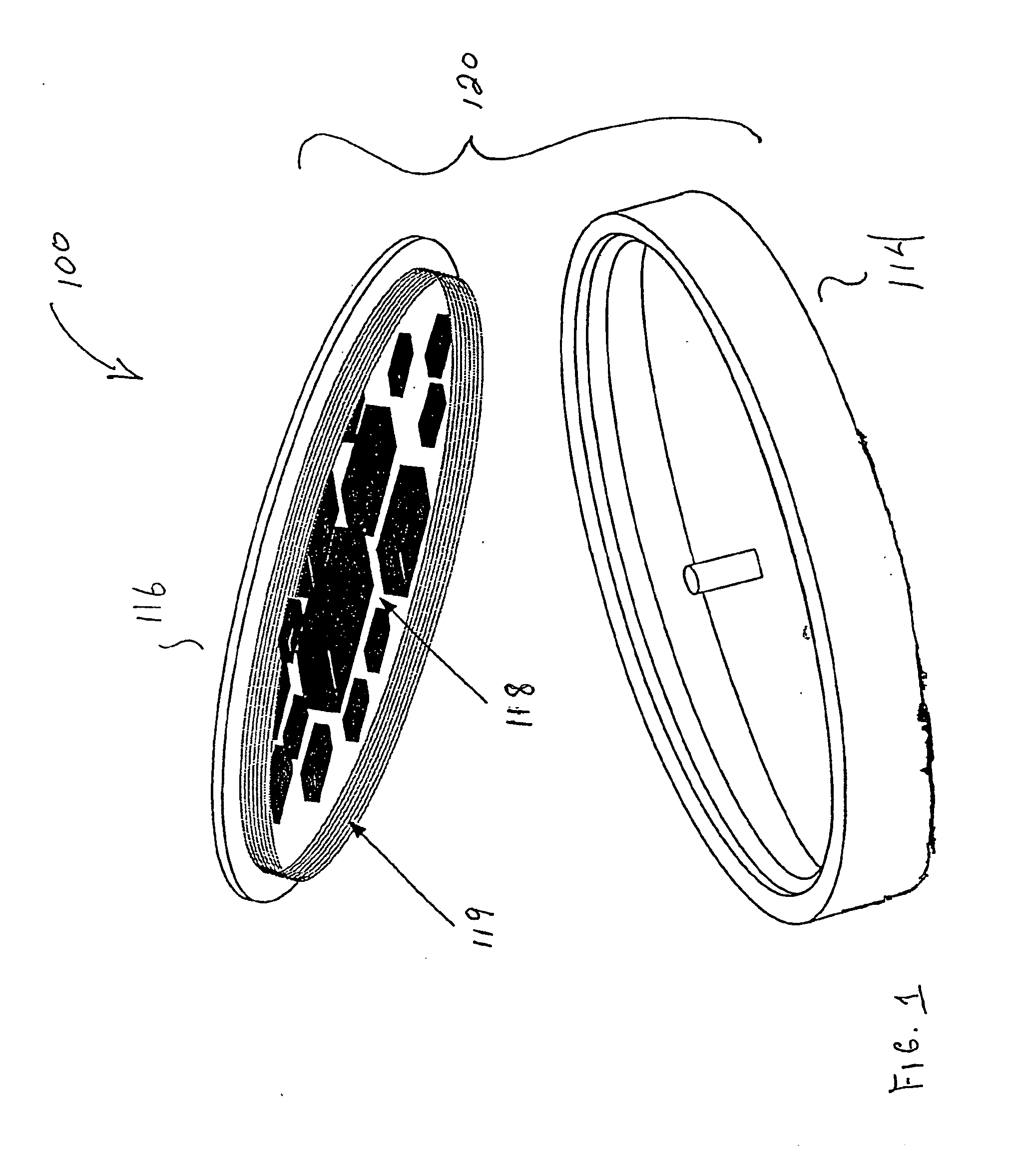
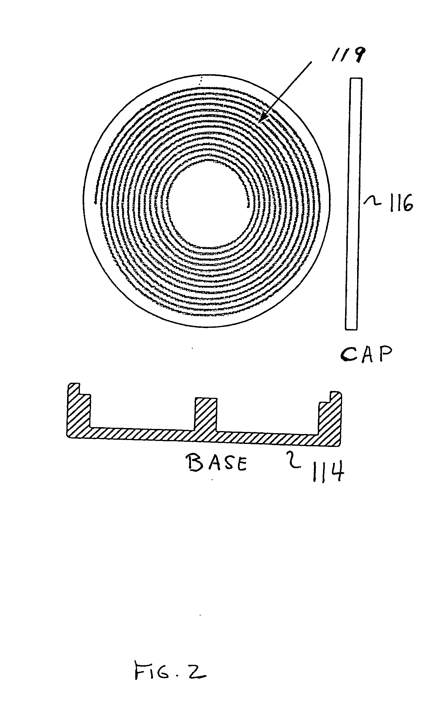
[0062] An important technical advantage of the present invention is that the circuitry of sensor platform 100 may be powered by an induction field sent by an interrogation unit. Thus, sensor platform 100 does not need a battery or other local power source or power storage. Because no battery is needed, sensor platform 100 and associated circuitry may be placed in the structure to be monitored and thereafter require little to no maintenance of sensor platform 100.

Problems solved by technology

One of the most important problems facing the nation is determining how to maintain the integrity of this system of roads and other structures at an acceptable cost.
By this time, remedial actions are more expensive than if the problem had been detected earlier.
In addition, significant degradation impacts repair schedules and quality of service for the bridge.
Yet another problem associated with present day sensor systems for use in bridge monitoring is that the sensors are not distributed throughout the bridge deck.
Instead, they are used only for discrete measurements, mostly due to economic limitations.
Furthermore, the cost of making measurements employing present day technology is high due to installation and monitoring requirements.
Further problems associated with prior art solutions for bridge monitoring is that recent research has focused on mechanical sensing such as stress / strain and pressure.
Sensors that are being designed to address corrosion-related degradation are limited to specific parameters such as, for example, chloride and temperature, or gross measurements of physical properties such as conductivity.

Method used


Image

  • Wireless multi-funtional sensor platform, system containing same and method for its use
  • Wireless multi-funtional sensor platform, system containing same and method for its use
  • Wireless multi-funtional sensor platform, system containing same and method for its use

Examples


Embodiment Construction

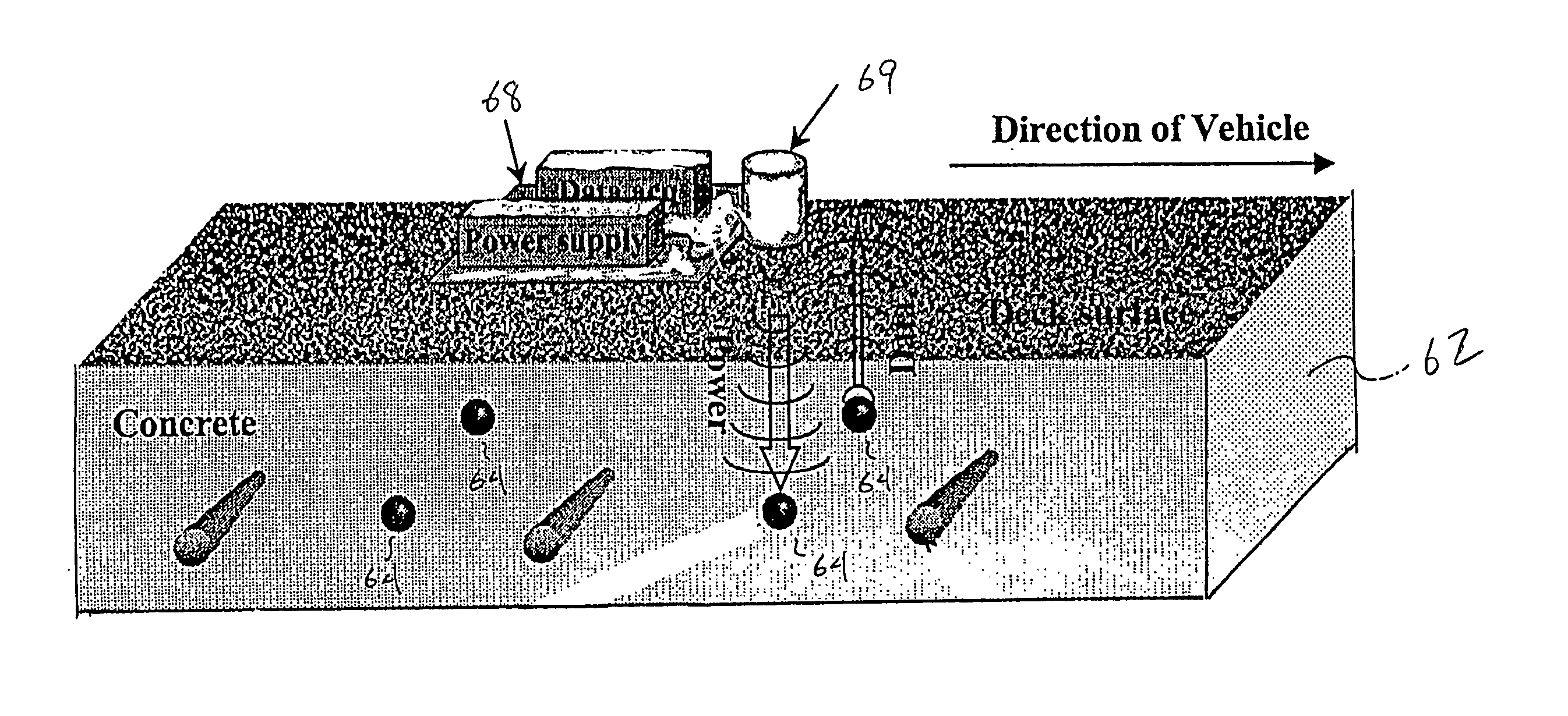
[0067] The operational concept of the multi-functional sensor system of the present invention is shown in FIG. 6 illustrating an exemplary application involving bridge monitoring. FIG. 6 illustrates a bridge structure 62 including a plurality of wireless embedded sensor platforms 64. For this particular application, the sensor platforms 64 are placed approximately every two meters throughout the structural elements of the bridge 62. The locations and densities of the sensor platforms 64 will depend on the particular structure being monitored.

[0068] As will be discussed below, information from the sensor platforms 64 will be transmitted during interrogation. The interrogation is performed with an interrogation unit 500 carried on a vehicle 68. The interrogation unit 500 records data from the sensor platforms 64 as the vehicle 68 passes in proximity to the sensor platforms 64. It should be understood that the interrogation unit 500 need not be carried on the vehicle 68, and may be han...


PUM


Abstract

A multi-functional sensor system for simultaneously monitoring various parameters such as the structural, chemical and environmental conditions associated with a medium to be monitored, e.g., bridges, high-rise buildings, pollution zones, is provided wherein the system includes at least a plurality of wireless multi-functional sensor platforms embedded in the medium in which an interrogation unit transmits power and receives responses. Each wireless multi-functional sensor platform includes multiple channels for accommodating a plurality of sensor types to simultaneously monitor the parameters associated with the medium. Thus, the wireless sensor platforms are formed to include those sensor types which are considered germane to the intended medium to be monitored.

Description

[0001] This application claims the benefit of prior filed, co-pending U.S. provisional application serial No. 60 / 254,118, filed on Dec. 8, 2000 and No. 60 / 284,018, filed on Apr. 16, 2001.[0002] 1. Field of the Invention[0003] The present disclosure generally relates to a wireless multi-functional sensor platform, a sensor system containing same and method for its use. More particularly, the present disclosure is directed to an in-situ multi-functional sensor system containing a plurality of wireless multi-functional sensor platforms and method for providing long-term monitoring of various parameters associated with a medium, e.g., concrete, by embedding the sensor system within the medium to predict the onset of degradation and thus aid in the scheduling of maintenance, management and repair thereof.[0004] 2. Description of the Related Art[0005] In the United States, billions of dollars have been spent in the construction of highways, freeways and their associated overpasses, bridge...

Claims


Application Information

Patent Timeline
Patent Type & Authority Applications(United States)
IPC IPC(8): E01D22/00E01D101/24G01D9/00G01D21/00G01D21/02G01M5/00G08B25/10G08C17/00
CPCG01D9/005G01D21/02G01M5/0008G01N33/383G01M5/0083G01M5/0091G01M5/0033
Inventor SRINIVASAN, REGASWAMYOSIANDER, ROBERTSPICER, JANE W.WEISKOPF JR, FRANCIS B.GROSSMANN, KENNETH R.CAIN, RUSSELL P.CARKHUFF, BLISS G.
Owner THE JOHN HOPKINS UNIV SCHOOL OF MEDICINE
Learn More