
Gas heating apparatus for chemical vapor deposition process and semiconductor device fabrication method using same

a technology of gas heating apparatus and chemical vapor deposition process, which is applied in the direction of lighting and heating apparatus, indirect heat exchangers, coatings, etc., can solve the problems of gas heating apparatus, limited prolongation of spiral-shaped quartz tubes, and bulky growth of gas heating apparatus

Inactive Publication Date: 2003-12-04
JUSUNG ENG
View PDF14 Cites 37 Cited by
  • Summary
  • Abstract
  • Description
  • Claims
  • Application Information

AI Technical Summary

Problems solved by technology

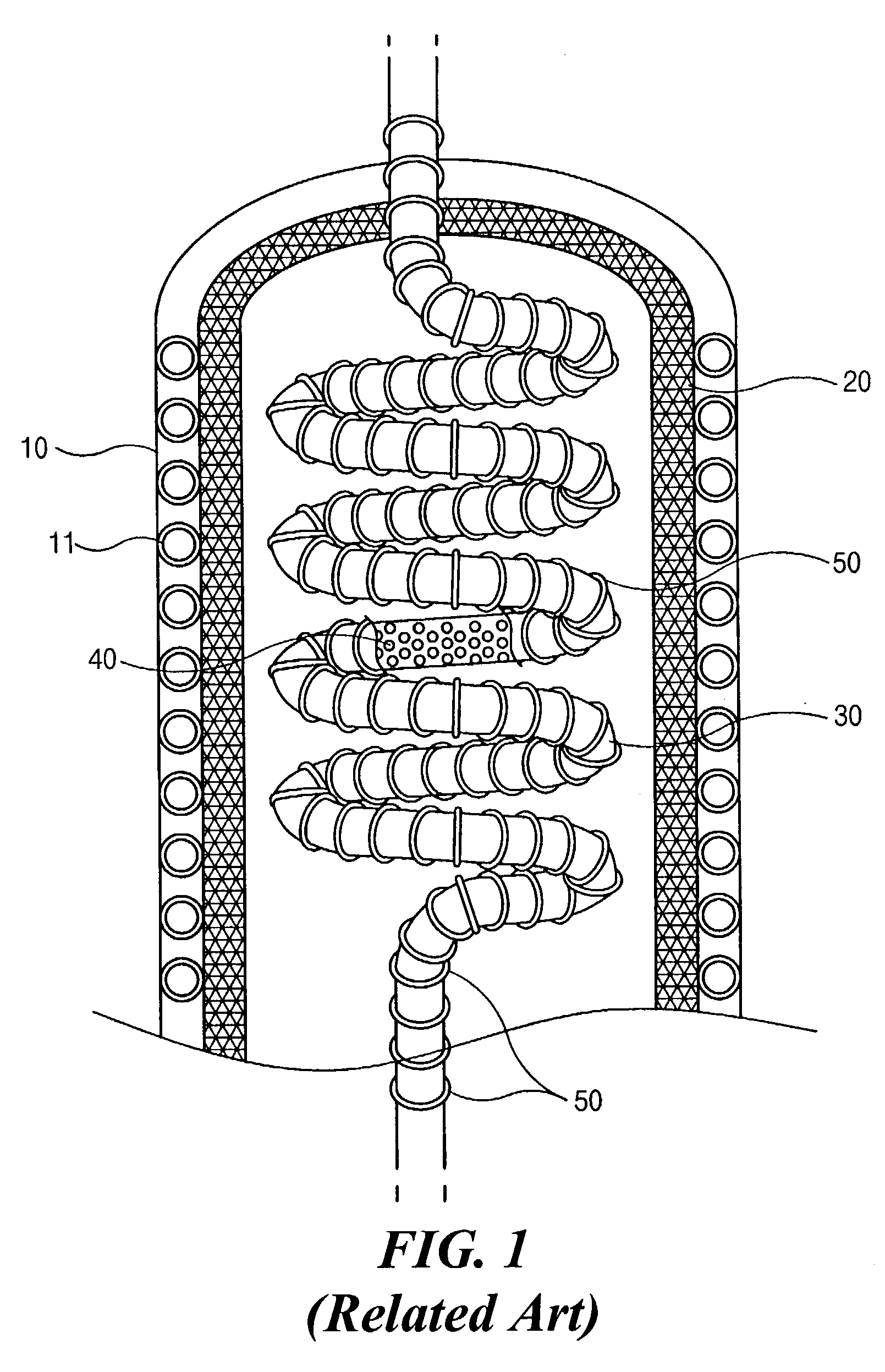
However, the gas heating apparatus of FIG. 1 has some disadvantages.
There is a limitation of prolonging the length of the spiral-shaped quartz tube 30 because, if do so, the gas heating apparatus of FIG. 1 becomes larger in bulk.

Method used


Image

  • Gas heating apparatus for chemical vapor deposition process and semiconductor device fabrication method using same
  • Gas heating apparatus for chemical vapor deposition process and semiconductor device fabrication method using same
  • Gas heating apparatus for chemical vapor deposition process and semiconductor device fabrication method using same

Examples


Embodiment Construction

[0021] Reference will now be made in detail to illustrated embodiment of the present invention, examples of which are shown in the accompanying drawings. Wherever possible, the same reference numbers will be used throughout the drawings to refer to the same or like parts.

[0022] FIG. 2 is a detailed portion cross sectional and partially cutaway view of a gas heating apparatus for the chemical vapor deposition according to the present invention. The arrows shown in FIG. 2 denote the flow of reaction gas.

[0023] In FIG. 2, the gas heating apparatus of the present invention for use in a chemical vapor deposition process includes a chamber 10, a heat insulating material 20, a quartz tube 100, a plurality of ceramic balls 40, and a heater 200,

[0024] The chamber 10 is a frame that becomes enclosures of the gas heating apparatus. A coolant passage 11 is disposed inside the chamber wall 10 so that the coolant flows through the coolant passage 11 and then cools down the chamber 10. The heat in...


PUM

PropertyMeasurementUnit
heat insulatingaaaaaaaaaa
shapeaaaaaaaaaa
diameteraaaaaaaaaa

Abstract

The present invention provides a gas heating apparatus that activates reaction gases for a chemical vapor deposition. The gas heating apparatus includes a chamber becoming enclosures of the gas heating apparatus; a heat insulating material 20 formed on an inner surface of the chamber so as to thermally insulate the inside of the chamber from the outside; a quartz tube having a gas inflow pipe, a gas outflow pipe, enlarged-pipe portions and abridged-pipe portion, wherein the enlarged-pipe portions and the abridged-pipe portions are alternately repeated and constitute a zigzag shape in an up-and-down direction in the chamber; a plurality of ceramic balls located inside the enlarged-pipe portions of the quartz tube; and a heater having a shape of coil spring and surrounding the zigzag shape of the quartz tube in the chamber.

Description

[0001] This application claims the benefit of Korean Patent Application No. 2002-0030999 filed on Jun. 3, 2002 in Korea, which is hereby incorporated by reference in its entirety for all purposes as if fully set forth herein.[0002] 1. Field of the Invention[0003] The present invention relates to an apparatus for use in a chemical vapor deposition process and a method for fabricating a semiconductor device. And more particularly, the present invention relates to a gas heating apparatus that previously applies heat to and then activates process gases for the chemical vapor deposition.[0004] 2. Description of Related Art[0005] The Chemical Vapor Deposition (CVD) is a process that reaction gases are introduced in a main chamber and then react with one another above a hot substrate to form a thin film, such as a SiO.sub.2 insulating film, or a tungsten (W) or aluminum (Al) thin film. In order to increase the efficiency of CVD process, the reaction gases are previously heated and then act...

Claims


Application Information

Patent Timeline
Patent Type & Authority Applications(United States)
IPC IPC(8): H01L21/205C23C16/44C23C16/452C23C16/455F28D17/00
CPCC23C16/452F28D17/005C23C16/4557
Inventor LIM, YOU-DONG
Owner JUSUNG ENG
Learn More