
Panel roller

Inactive Publication Date: 2003-11-20
PROPLAS
View PDF13 Cites 13 Cited by
  • Summary
  • Abstract
  • Description
  • Claims
  • Application Information

AI Technical Summary

Benefits of technology

[0005] The present invention provides a roller which is light in weight, which is easy to assembly and which does not deteriorate due to climatic conditions.
[0007] The molded construction of the roller provides very accurate roller parts at a very affordable price. Furthermore, the synthetic construction of the roller makes it extremely light in weight and durable compared to prior art metal rollers.

Problems solved by technology

On a relatively large door the number of rollers required add to the weight of the door due to the metal construction of the rollers.
Also the rollers themselves are often susceptible to rusting particularly when they face outdoor weather conditions.

Method used


Image

  • Panel roller
  • Panel roller
  • Panel roller

Examples


Embodiment Construction

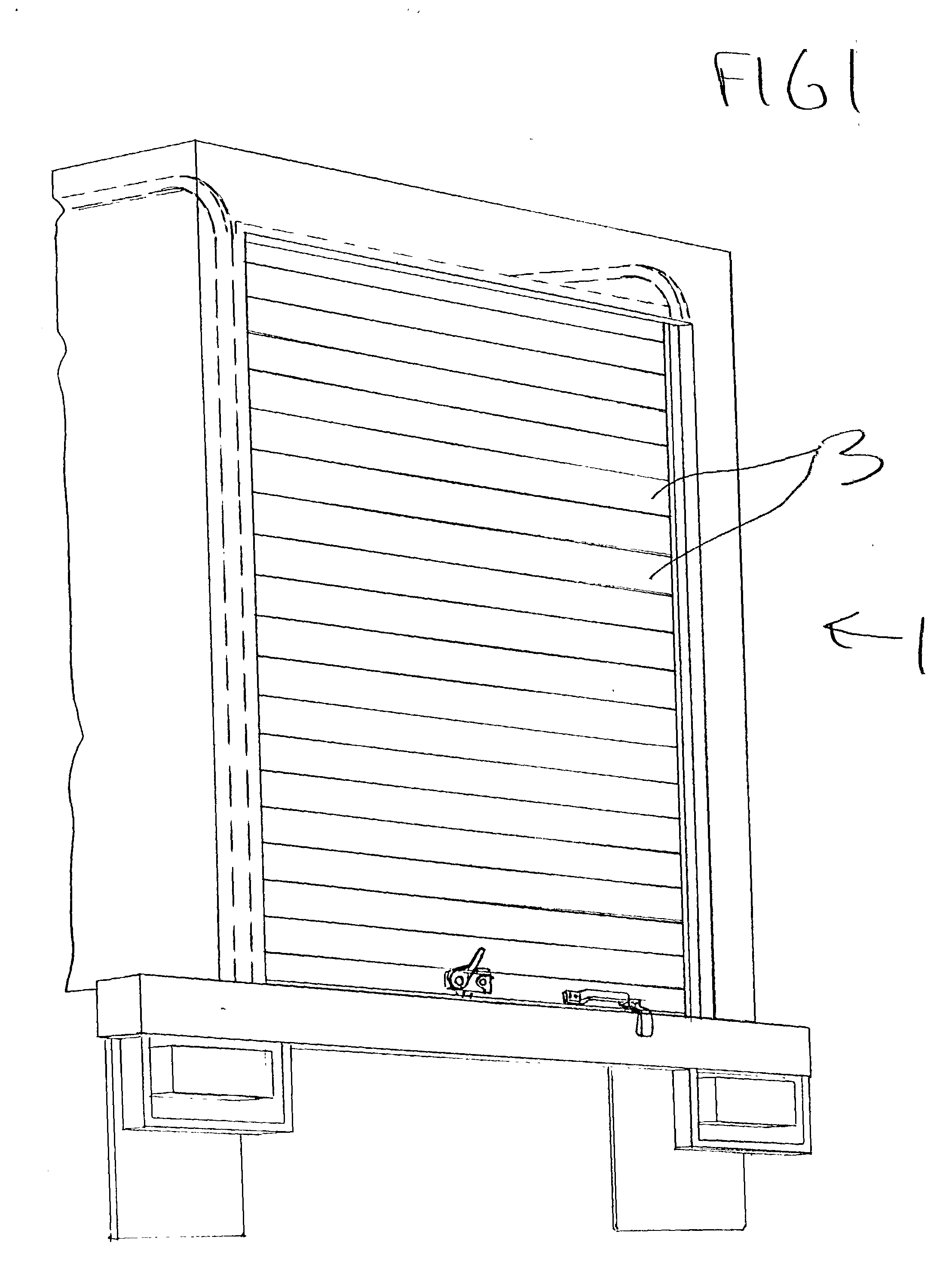
[0021] FIG. 1 shows the rear end of a truck trailer. The truck trailer is opened and closed by a rolling door generally indicated at 1. This rolling door comprises a plurality of panels 3 hingedly secured to one another. The panels preferably have a resin construction.

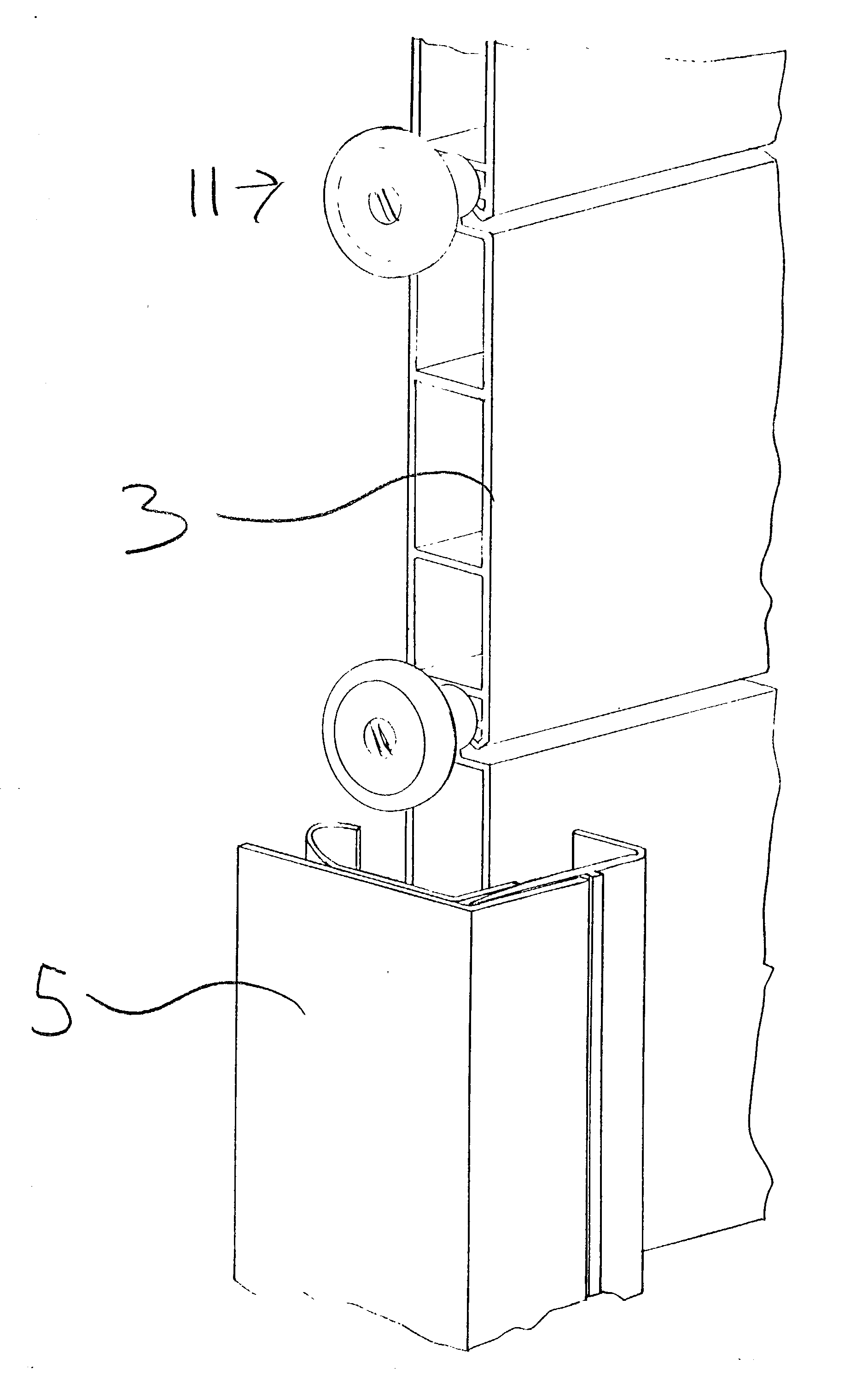
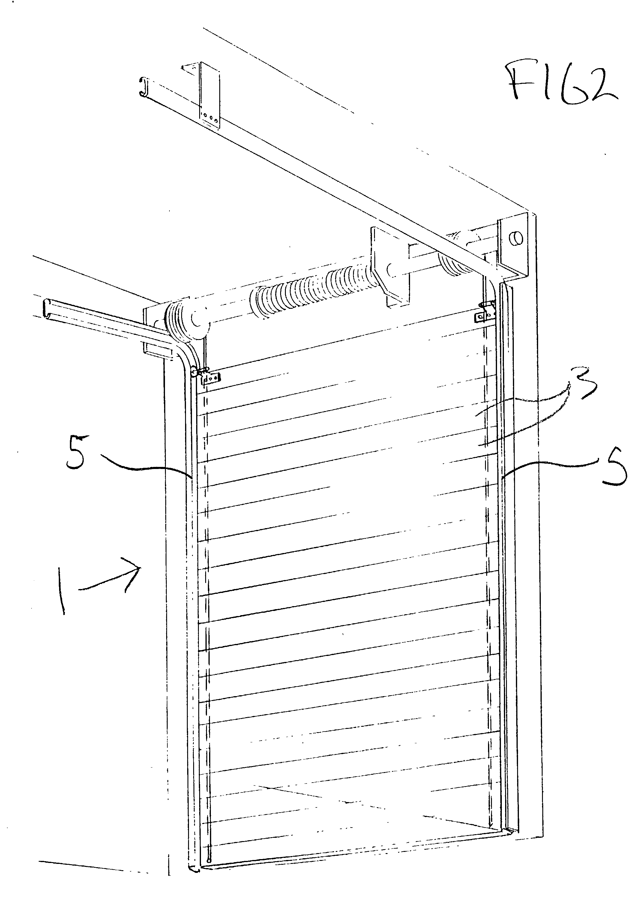
[0022] FIG. 2 shows that the trailer to the inside of door 1 is provided with a pair guide channels 5 to each side of the door.

[0023] As will be seen in FIG. 3 of the drawings rollers 11 ride the panels 3 along the guide channels 5.

[0024] FIGS. 4 and 5 of the drawings show that each of the panels 3 is provided to one end with a hollow head 7 and to the other end with an undercut opening 11. Head 7 slides into opening 11 to provide a hinged connection between the adjacent panels as shown in FIG. 5 of the drawings. The hollow head 7 provides an opening 9 for receiving one of the rollers 11 between each of the panels at opposite sides of the door.

[0025] The roller itself is best described having reference to FIGS. 6 throu...


PUM


Abstract

A roller which fits into and rides a panel along a guide channel has a molded synthetic roller head and a molded synthetic roller shaft. The head and the shaft are made separately from and then attached to one another. The roller head has a center opening and the roller shaft has an end part which is trapped in the center opening of the roller head without requiring the use of separate fasteners.

Description

[0001] The present invention relates to a roller used to roll a panel along a guide channel for the panel.[0002] Guide rollers for panels are known in the prior art. These guide rollers are often used in a rolling door construction such as for example, a hinged garage door. The head of the roller is trapped in a guide channel beside the garage door and the shaft of the roller is secured by some type of bracket to the inside of the garage door.[0003] The known guide rollers for rolling doors have a metal construction with the head and shaft of the roller being secured by some type of a mechanical fastener.[0004] On a relatively large door the number of rollers required add to the weight of the door due to the metal construction of the rollers. Also the rollers themselves are often susceptible to rusting particularly when they face outdoor weather conditions.SUMMARY OF THE PRESENT INVENTION[0005] The present invention provides a roller which is light in weight, which is easy to assemb...

Claims


Application Information

Patent Timeline
IPC IPC(8): B60J5/14E05D1/04E05D15/16E05D15/24E06B9/58
CPCB60J5/14E05D1/04E05D15/165E05D15/242Y10T16/364E05Y2900/106E06B9/582E06B2009/1588E05Y2201/688E05Y2900/00
Inventor PERKS, TOM
Owner PROPLAS
Learn More