System and method for load-sharing computer network switch
a computer network switch and load-sharing technology, applied in the field of system and method for load-sharing computer network switch, can solve the problems of excess bandwidth of switch fabric redundancy, packet switching, and inability to create dedicated links through the switch
- Summary
- Abstract
- Description
- Claims
- Application Information
AI Technical Summary
Problems solved by technology
Method used
Image
Examples
example 1
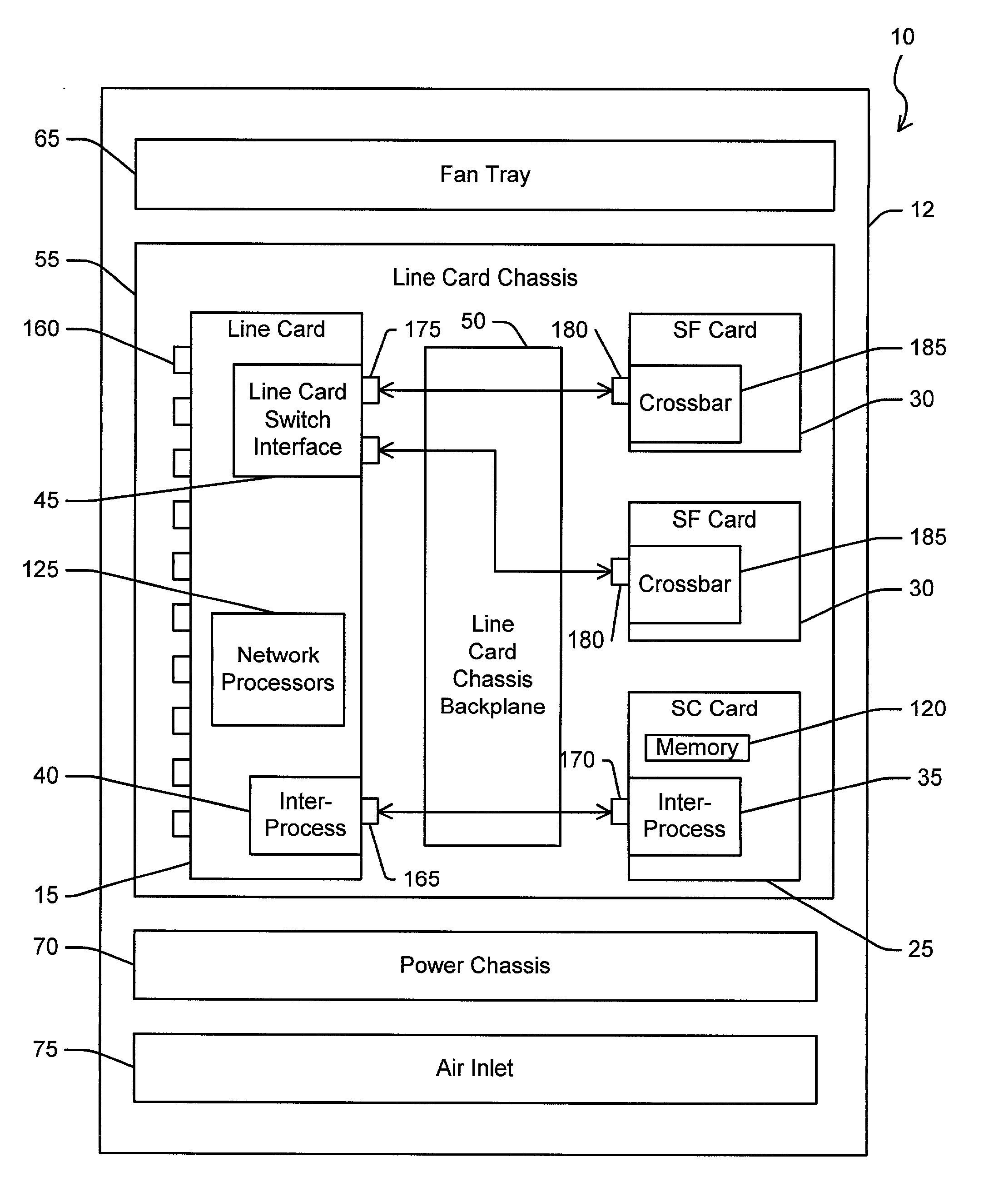
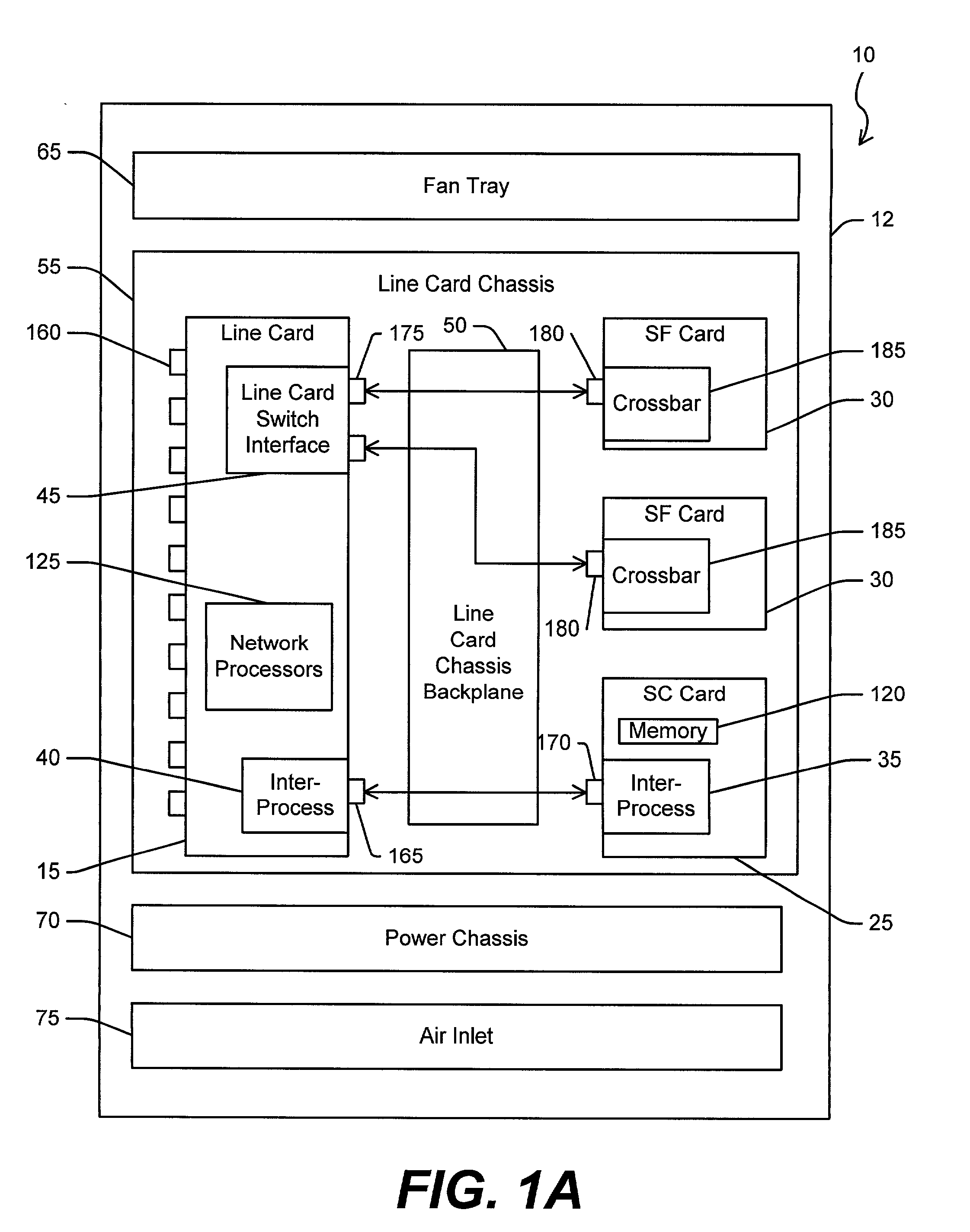
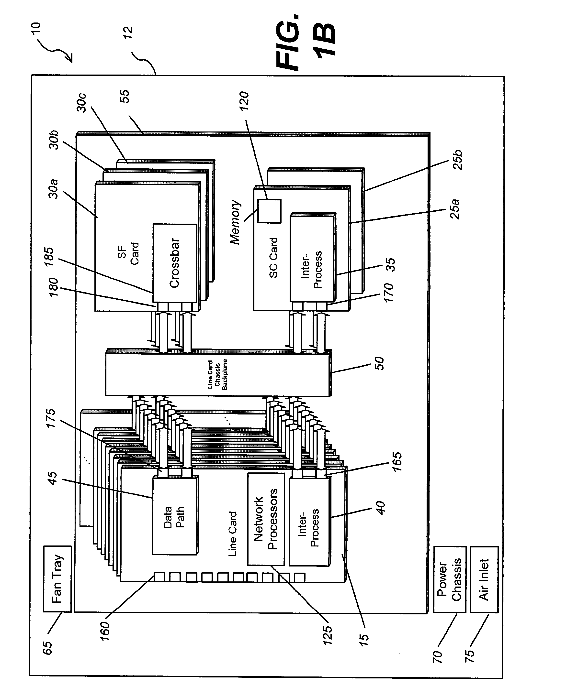
[0043] The switch system of the present invention may also be configured as an active / active redundancy system. The switch system can be designed using load-sharing and multiple ZSF200X chips or switch fabric cards for redundancy. In this configuration, at least two switch fabric cards are active, e.g., a load-sharing configuration, and at least one switch fabric card may serve as a redundant card. However, in an exemplary embodiment of the present invention, the load-sharing may be accomplished through the use of multiple ZSF200X chips, rather than multiple switch fabric cards. For instance, the channels or signal pairs for each line card may be divided between each ZSF200X chip, or each switch fabric card in the switch system, e.g., both the active and redundant ZSF200X chips and / or switch fabric cards. In the load-sharing configuration, each line card would then distribute its traffic across each active ZSF200X chip or active switch fabric card.
[0044] Referring to the switch syst...
example 2
[0051] The switch system may accommodate a multiple switch fabric configuration. The signal pairs or channel may be divided between the primary switch slot and the secondary switch slot(s). For example, in one exemplary embodiment, the switch system may be designed to accommodate two switch fabric cards, although use of a single switch fabric card is possible with reduced bandwidth performance. For an exemplary embodiment with a 24-channel dual switch fabric configuration, these 24 signals may be split with 12 going to the primary switch slot and the second group of 12 going to the secondary switch slot. A single chassis configuration can operate with a single switch card (e.g., 12 lines). For an exemplary embodiment utilizing the ZSF200X chip set, the switch card may contain three ZSF200X chips and can carry 9.6 Gbits / sec of traffic. For redundancy, a second switch fabric card can be added. Note however, in load-sharing mode the line card (e.g., ZSF202Q) would automatically spread ...
example 3
[0054] The fabric switch system of the present invention may utilize any number of lines depending on the hardware that is utilized, e.g., other than the 24-channel configurations discussed above. To reduce the system serial count link, the above-discussed exemplary embodiments may use chip sets that are configured in a load-sharing mode (e.g. as opposed to 16:16 redundancy). For example, the present disclosure discusses the use of the ZSF202Q and ZSF200X chips in the load-sharing mode. A person of ordinary skill in the pertinent arts should understand that any suitable chip set may be used and the present invention is not limited to the ZSF202Q or ZSF200X chip set discussed herein.
[0055] Generally, load-sharing does not place a minimum on the number of lines that need to connect from each line card to each switch fabric card (e.g., from each ZSF202Q to each ZSF200X). However, for a particular selection of chip sets or other components, the system may be limited to a maximum number ...
PUM
 Abstract
Description
Claims
Application Information
 - R&D
- Intellectual Property
- Life Sciences
- Materials
- Tech Scout
- Unparalleled Data Quality
- Higher Quality Content
- 60% Fewer Hallucinations
Browse by: Latest US Patents, China's latest patents, Technical Efficacy Thesaurus, Application Domain, Technology Topic, Popular Technical Reports.
© 2025 PatSnap. All rights reserved.Legal|Privacy policy|Modern Slavery Act Transparency Statement|Sitemap|About US| Contact US: help@patsnap.com


