
Electric grill with food divider

a technology of electric grills and food dividers, which is applied in the field of electric grills, can solve the problems of increasing the overall cooking time, indoor grills are unsuitable for preparing foods, and affecting the overall cooking time of the grills

Inactive Publication Date: 2003-10-23
GROHS ROBERT L
View PDF4 Cites 25 Cited by
  • Summary
  • Abstract
  • Description
  • Claims
  • Application Information

AI Technical Summary

Benefits of technology

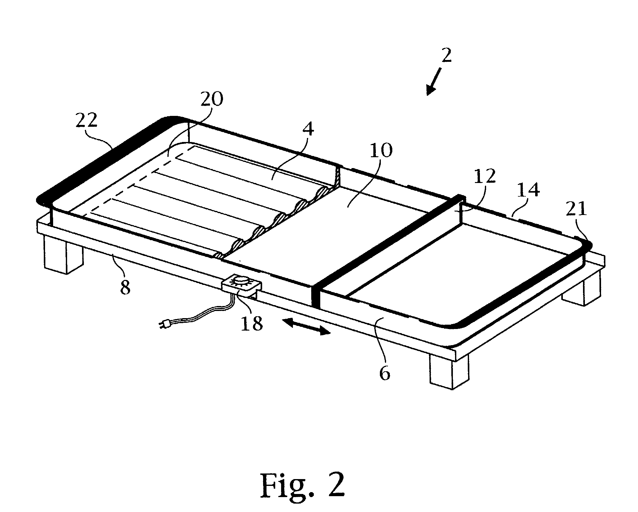
[0014] It is still another objective of the present invention to provide one cooking surface enclosed by four shallow walls, adjoined with two handles one on each end, to lift the electric grill unit up and off the base platform for easy cleaning and to pour off liquids.
[0017] It is still anther objective of the present invention to place the food divider in many positions on the flat surface for cooking or detach it for easy cleaning of the electric grill.
[0022] It is still a further objective of the present invention to provide a stable base or platform from which the electric grill can easily be removed and not encumbered.
[0023] It is still a further objective of the present invention to provide a stable base of heat resistant plastic which elevates the electric grill over a counter.

Problems solved by technology

Unfortunately each of the above grills is hampered by the miniature size of the cooking surfaces.
The result has been that indoor grills are unsuitable for preparing foods for more people or more types of food using one unit.
When preparing foods on an indoor grill, the cook is forced to make smaller amounts of food at a time which increase the overall cooking time, and may require the host to serve food in waves, rather than serving everyone at once.
A further difficulty with indoor grills is found in the limited types of food that can be grilled or cook on the same unit.
A griddle has no shallow wall to push food against for turning purposes and grease may spill over the lip edge.

Method used


Image

  • Electric grill with food divider
  • Electric grill with food divider
  • Electric grill with food divider

Examples


Embodiment Construction

[0062] Referring to alternate FIG. 15, ribbed grilling surface 64 may have a level or horizontal top grilling surface, comprising ribs 65 lying parallel to each other, said ribs are separated by channels 66 that slope downwardly into an open reservoir 67.

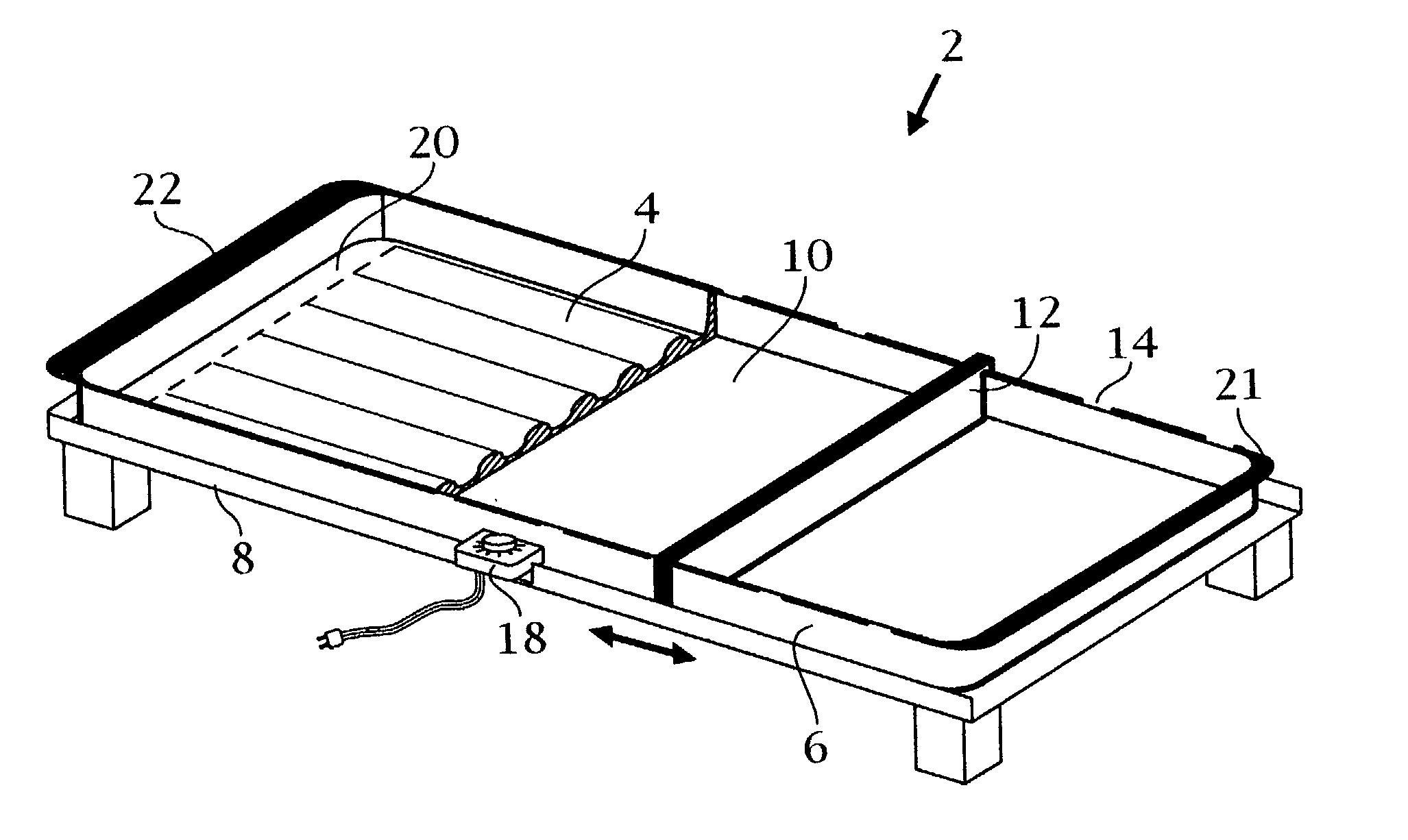
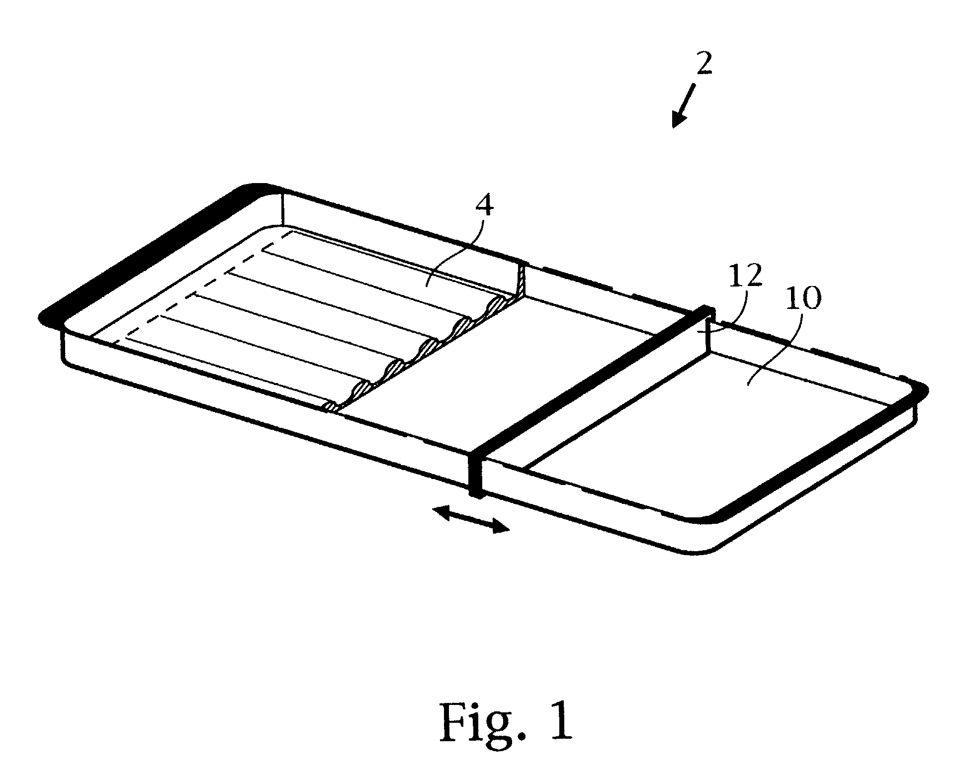
[0063] With reference to alternate FIG. 16, the top view of shallow wall 6 may be designed with one smooth wall surface; without grooves. With reference to FIG. 2 this design enables the food divider 12 to be placed down on the shallow wall 6, in any positioned required; not only in grooves 14. With reference to FIG. 6., food divider 12 with open grooves 13, must have tight tolerances to restrict unwanted liquids.

[0064] Having now fully set forth the preferred embodiments and certain modifications of the concept underlying the present invention, various other embodiments as well as variations and modifications of the embodiments herein shown and described will obviously occur to those skilled in the art upon becoming familiar with s...


PUM


Abstract

An electric grill comprising a primary cooking unit that is defined as a ribbed grilling surface adjoined by a planar cooking surface with four shallow walls around the unit and an adjustable food divider used to separate food from liquids, when positioned on the primary unit. The ribbed surface is for grilling foods and the flat surface is suitable for cooking foods. The ribbed surface has channels between the ribs that carry away liquids and grease while cooking. A reservoir at the end of the ribbed surface collects the runoff. The parallel ribs slope downwardly to the reservoir area. Placement of the food divider within the primary unit, will yield two or three cooking compartments. Liquids from food, are contained in different areas on the primary unit, when the food divider is in use. A thermostat with an on-off control is used to select any desired temperature for cooking. The primary cooking unit sits on a platform base structure that is not attached or encumbered to the primary unit. The electric grill uses the food divider to separate food to prevent the loss of flavor and also to restrict the mixing of unwanted liquids as excess water and grease, generated while cooking.

Description

[0001] The present application is based on U.S. provisional application (serial No. 60 / 373,305, Filed on Apr. 18, 2002 by Robert Grohs for his "ELECTRIC GRILL AND GRIDDLE WITH REMOVABLE FOOD DIVIDER)."BACKROUND OF THE INVENTION[0002] 1. Field of the Invention[0003] The present invention relates to cookware and in particular an electric grill comprising a ribbed grilling surface adjoined with a flat cooking surface, with an adjustable food divider that is used to separate food from liquids when positioned on the flat cooking surface.[0004] 2. Description of the Background[0005] There is a market for portable cooking devices, and a number of indoor grills were manufactured to meet this demand. Indoor cooking grills are characterized by a heated cooking surface, which uses either electric or gas to cook. One design prevalent in the background art incorporates a clamshell type hinged lid comprising an upper and lower surface. In the closed position, both surfaces cook the food. U.S. Pat...

Claims


Application Information

Patent Timeline
IPC IPC(8): A47J37/06
CPCA47J37/0676
Inventor GROHS, ROBERT L.
Owner GROHS ROBERT L
Learn More