
Separator in lead acid battery and manufacturing method thereof

a lead acid battery and separator technology, applied in the direction of cell components, electrical equipment, cell component details, etc., can solve the problems of low resistance when, low capacity of battery, high chemical stability and lower price, etc., to reduce the thickness of the separator, increase the number of positive and negative plates, and save space in the interior.

Inactive Publication Date: 2003-09-18
CSB BATTERY CO LTD
View PDF0 Cites 11 Cited by
  • Summary
  • Abstract
  • Description
  • Claims
  • Application Information

AI Technical Summary

Benefits of technology

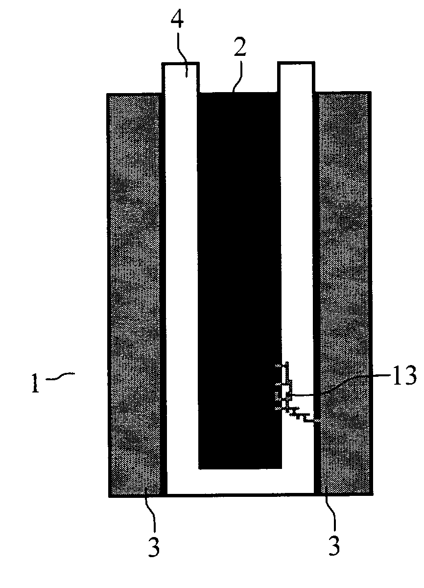
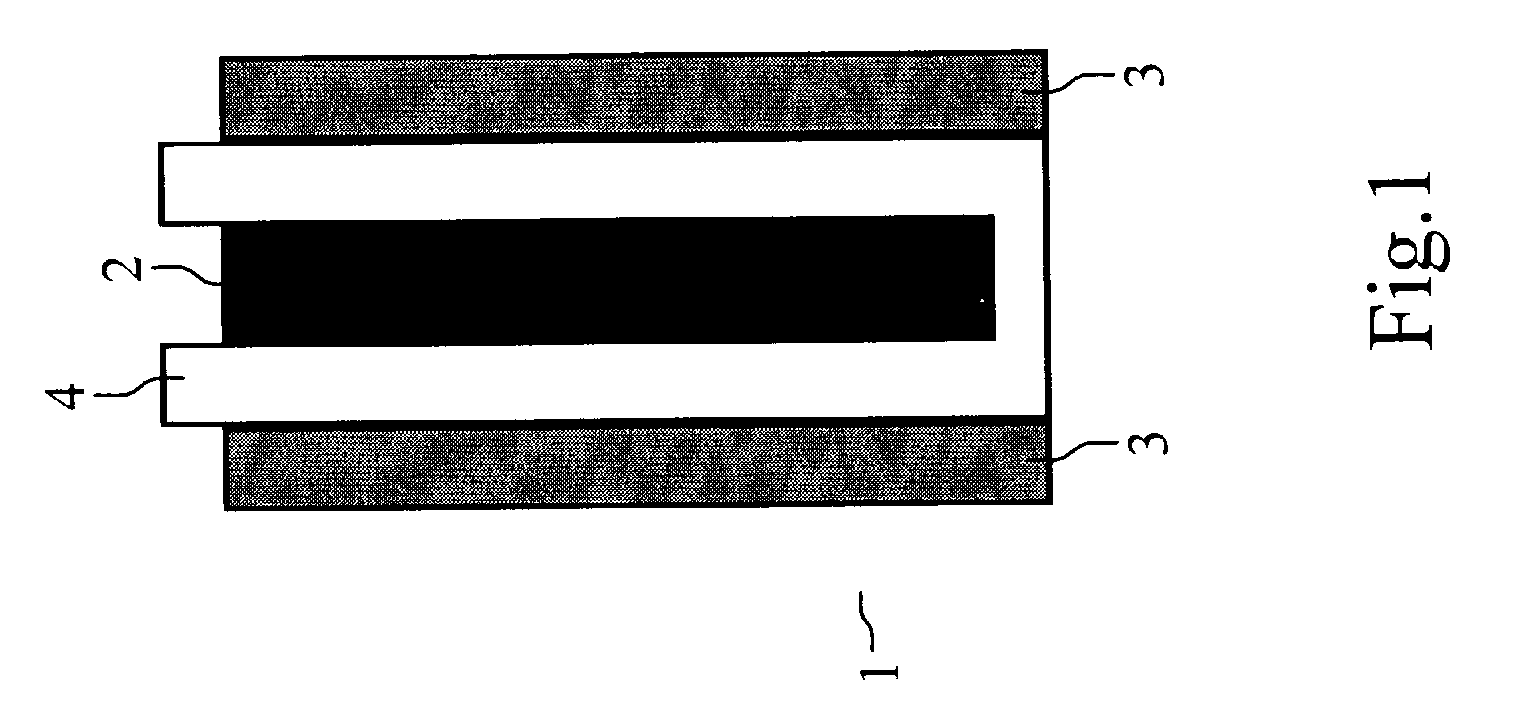
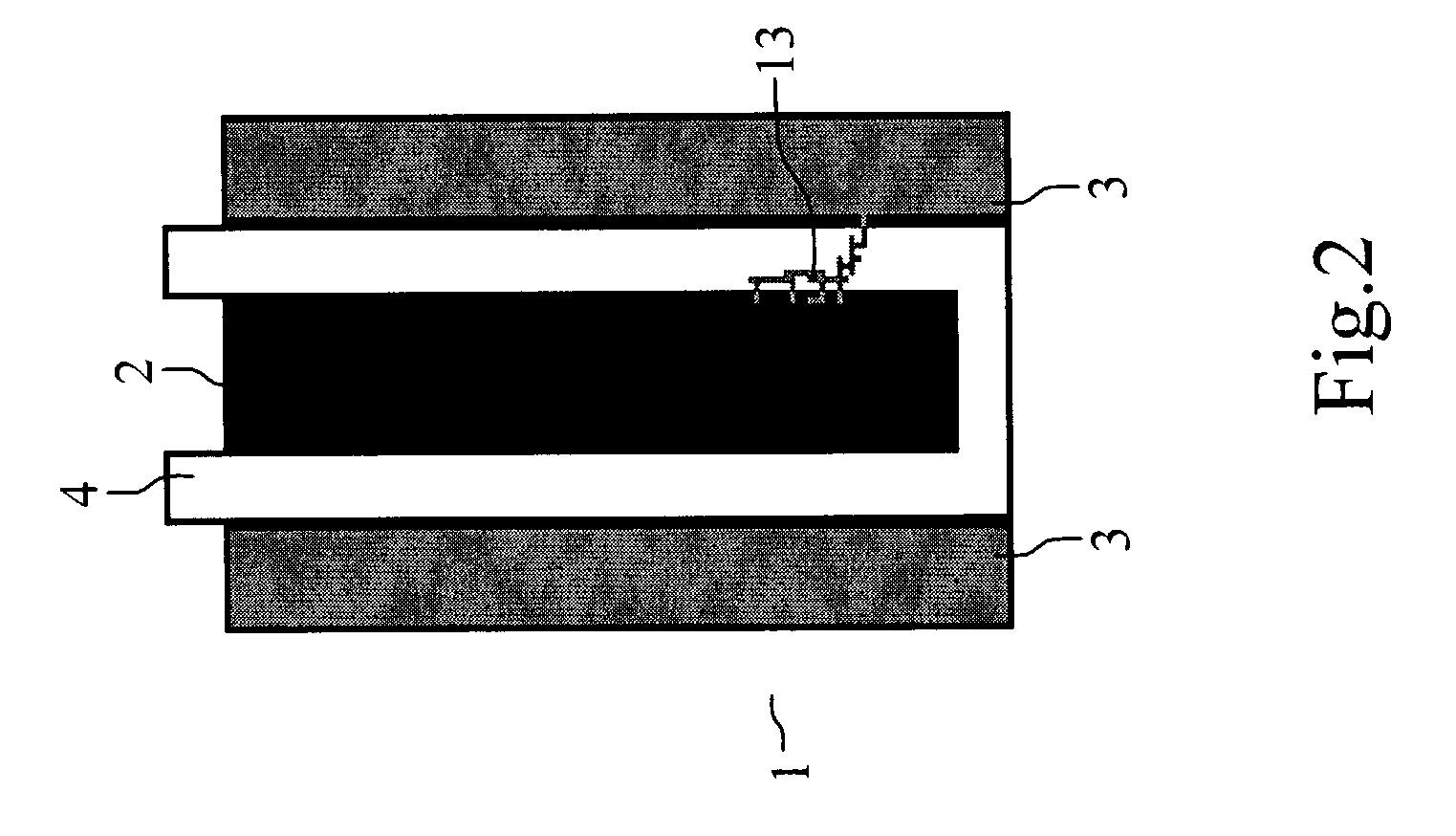
[0017] The foregoing polymers possess characteristics as follows: acid-resistance capability, able to form, porous layer that allows acid transfer or being the medium of the acid transfer, and enough bonding strength so as to bind fibers, thus increasing the mechanical strength of the porous separator.
[0062] It can be concluded from the embodiments above that, the battery separator of the invention can decrease the thickness of the separator, thus saving space occupied in the interior of batteries, increasing the numbers of the positive and negative plates, and raising the capacity of the battery.

Problems solved by technology

General functional requirements for separators are mainly: low resistance when adsorbing acid, high chemical stability and lower price.
However, the disadvantage is that the capacity of battery is lowered.
However, the conventional AGM separator contains certain drawbacks, for example, to decrease the thickness of the separator is to lower the mechanical strength, thus causing problems during manufacturing process; furthermore, thinner AGM separators also tend to cause shortage, with possible reasons being that, during the manufacturing process some small lead drops or dusts are to be formed on the surface of the electrode plates, thus if the AGM separators are too thin, the lead drops or dusts shall potentially cause the shortage between the positive and negative electrodes.
Moreover, the battery separator produced via means provided by the invention not only increases the mechanical strength, but also decreases the possibility of the shortage.

Method used


Image

  • Separator in lead acid battery and manufacturing method thereof
  • Separator in lead acid battery and manufacturing method thereof
  • Separator in lead acid battery and manufacturing method thereof

Examples


embodiment 2

Testing for the Performance of the Separator

[0059] Through the test result of the embodiment 1 above, the glass fiber separator having polymers coated manufactured via method of the invention has more mechanical strength, therefore two lead-acid batteries (A and B) with identical sizes are to be compared in this embodiment, wherein the separator in battery A is a thicker glass fiber separator commonly used, whereas the separator in battery B is that manufactured via the method of the invention. Thus separator used in battery B has higher mechanical property; thinner separator could be used and more positive and negative electrode plates (compare to battery A) were installed inside battery B.

[0060] The means for testing the efficiency of the two batteries is to conduct high rate discharge with certain current (e.g., 36 amperes), and at. the same time observe the variations of the voltage of the batteries. Basically, during the process of continuous high rate discharge, the voltage of...


PUM

PropertyMeasurementUnit
thicknessaaaaaaaaaa
widthaaaaaaaaaa
lengthaaaaaaaaaa

Abstract

The invention provides a separator in lead acid battery, composed of fiber material and polymers; the polymers provide functions of increasing the mechanical strength for separators, avoiding shortage between positive and negative electrodes, and decreasing the thickness of separators. The invention also provides a manufacturing method of battery separators, whereby polymers are used to coat or absorb to porous separators through means of spraying, immersing, brushing, adhering or other similar means, thus acquiring thinner battery separators with increased mechanical strength.

Description

[0001] 1. Field of the Invention[0002] The invention relates to a separator for lead acid battery and the manufacturing method thereof; with the porous separator being coated or attached or impregnated with polymers, the mechanical strength of the separator is to be increased, the thickness thereof decreased and shortage avoided.[0003] 2. Background of the Invention[0004] During daily life, the use of batteries has become extremely prevalent, with the kinds of batteries being categorized, according to characteristics of charging and discharging electricity and nature of functions, as primary cells and secondary battery, wherein the secondary batteries refer to batteries that can be repeatedly used by the process of charging which, enabling the activated material in batteries to recover to the original state, makes the continuing provision of electricity by using the same batteries possible. The secondary batteries include lead-acid batteries, Ni--Cd batteries, Ni--MH batteries, seco...

Claims


Application Information

Patent Timeline
Patent Type & Authority Applications(United States)
IPC IPC(8): H01M10/06H01M50/403
CPCH01M2/145Y02E60/126H01M2/1606Y02E60/10H01M50/44H01M50/403
Inventor CHEN, RICHARDHO, CHIEN-HSIENPHANTHAPIRAT, THAWEECHAIMARTINEZ, ALEJANDRO
Owner CSB BATTERY CO LTD
Learn More