
Radio communication system, radio communication control apparatus, radio communication control method, and computer program

a radio communication system and control apparatus technology, applied in the field of radio communication systems, radio communication control apparatuses, radio communication control methods, computer programs, etc., can solve the problems of inconvenient use of the constructed system, complicated cable wiring, and difficulty in constructing networks with eas

Inactive Publication Date: 2003-09-11
SONY CORP
View PDF15 Cites 195 Cited by
  • Summary
  • Abstract
  • Description
  • Claims
  • Application Information

AI Technical Summary

Benefits of technology

[0031] It is therefore a main object of the present invention to provide an excellent wireless communication system which allows the coexistence of a plurality of mutually contending wireless networks and an excellent wireless communication control apparatus and method and an excellent computer program which preferably control the communications operation in each communication network in a communication environment in which a plurality of wireless networks contend with each other.
[0032] It is another object of the present invention to provide an excellent wireless communication system which allows the coexistence of a plurality of wireless networks contending with each other in a same frequency band, an excellent wireless communication control apparatus and wireless communication control method, and an a computer program which preferably control the communications operation in each communication network in a communication environment in which a plurality of wireless networks contend with each other in a same frequency band.
[0033] It is still another object of the present invention to provide an excellent wireless communication system, an excellent wireless communication control apparatus and wireless communication control method, and an excellent computer program which, if a plurality of personal area networks exist on a same frequency channel, allow the coexistence of these personal area networks by time-division multiplexing transmission frame periods only by performing control between transmission apparatuses which provide control stations.

Problems solved by technology

This requires line laying work, making it difficult to construct networks with ease and making cable wiring complicated.
After the construction of a LAN, the moving range of apparatuses is limited by the cable lengths, thereby making it inconvenient to use the constructed system.
On the other hand, an impulse signal train used in the UWB wireless communication scheme has no particular frequency carrier, so that it is difficult to perform a carrier sense operation.
Therefore, if the UWB wireless communication scheme is applied as the PHY layer of the IEEE 802.15.3, the carrier sense standardized by this section cannot be used for access control because there is no particularly carrier signal, thereby having to resort to the access control based on time division multiplexing.
However, this method in which each terminal station reports to the control station requires a means for reporting to the control station from time to time, thereby presenting a problem of increasing the frequency of reporting if there are plural adjacent networks.
In addition, the above-mentioned method, because the usage status of each slot is known by detecting a predetermined synchronous signal, all frame structures used by other networks cannot be understood.
In other words, if plural networks coexist in the same space, the request for channel bandwidths has no relationship with how to solve the problem of contention between the base stations.
Further, the above-mentioned Japanese patent publication does not solve the problems of the contention between networks and dynamic assignment of time slots (or resources) in the case where a new network is constructed in the same space or a network moves to this same space from another space.

Method used


Image

  • Radio communication system, radio communication control apparatus, radio communication control method, and computer program
  • Radio communication system, radio communication control apparatus, radio communication control method, and computer program
  • Radio communication system, radio communication control apparatus, radio communication control method, and computer program

Examples


Embodiment Construction

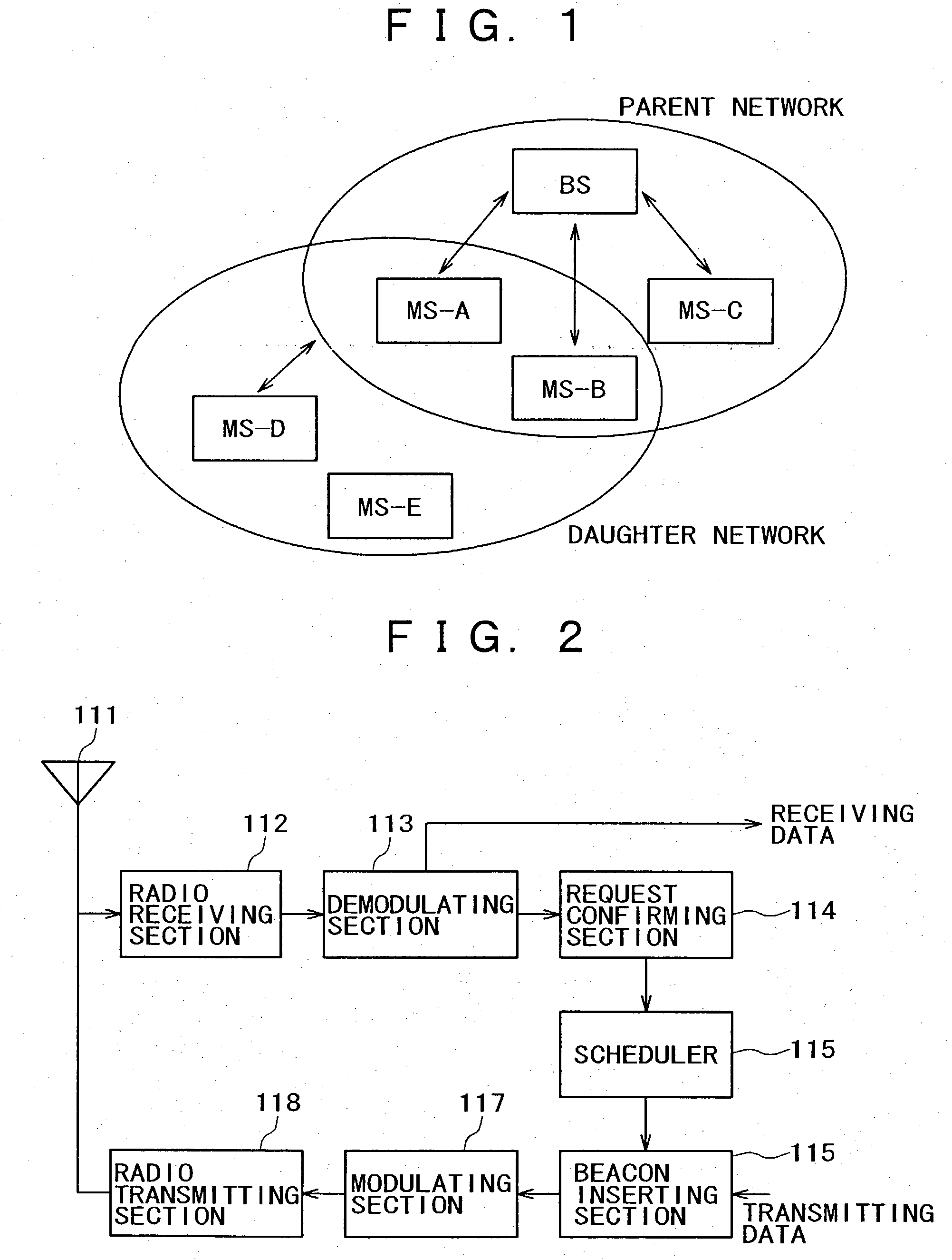
[0248] .fwdarw.RECEIVING DATA

[0249] 114 REQUEST CONFIRMING SECTION

[0250] 115 SCHEDULER

[0251] 115 BEACON INSERTING SECTION

[0252] .rarw.TRANSMITTING DATA

[0253] 117 MODULATING SECTION

[0254] 118 RADIO TRANSMITTING SECTION

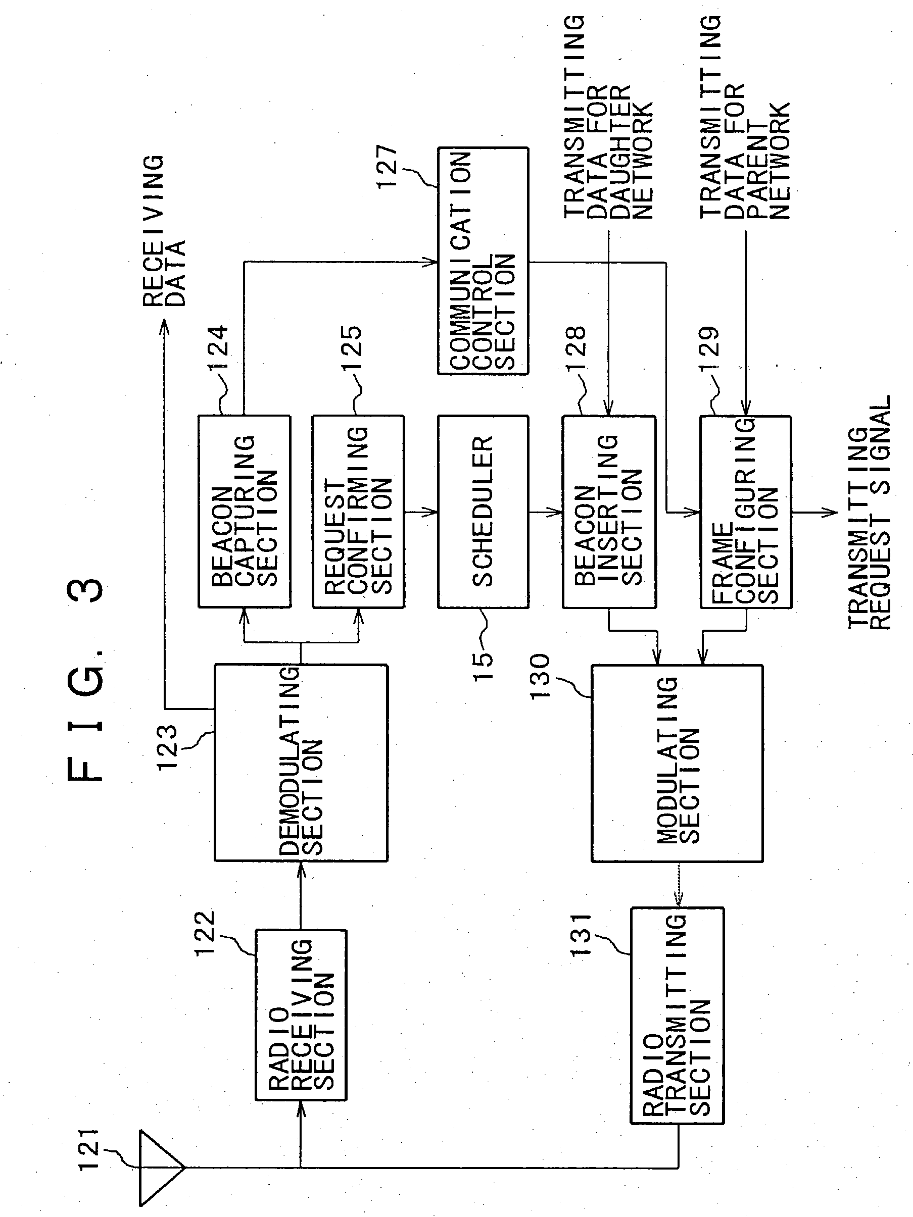
[0255] FIG. 3

[0256] 122 RADIO RECEIVING SECTION

[0257] 123 DEMODULATING SECTION

[0258] .fwdarw.RECEIVING DATA

[0259] 124 BEACON CAPTURING SECTION

[0260] 125 REQUEST CONFIRMING SECTION

[0261] 15 SCHEDULER

[0262] 127 COMMUNICATION CONTROL SECTION

[0263] 128 BEACON INSERTING SECTION

[0264] .rarw.TRANSMITTING DATA FOR DAUGHTER NETWORK

[0265] 129 FRAME CONFIGURING SECTION

[0266] .rarw.TRANSMITTING DATA FOR PARENT NETWORK

[0267] .dwnarw.TRANSMISSION REQUEST SIGNAL

[0268] 130 MODULATING SECTION

[0269] 131 RADIO TRANSMITTING SECTION

[0270] FIG. 4

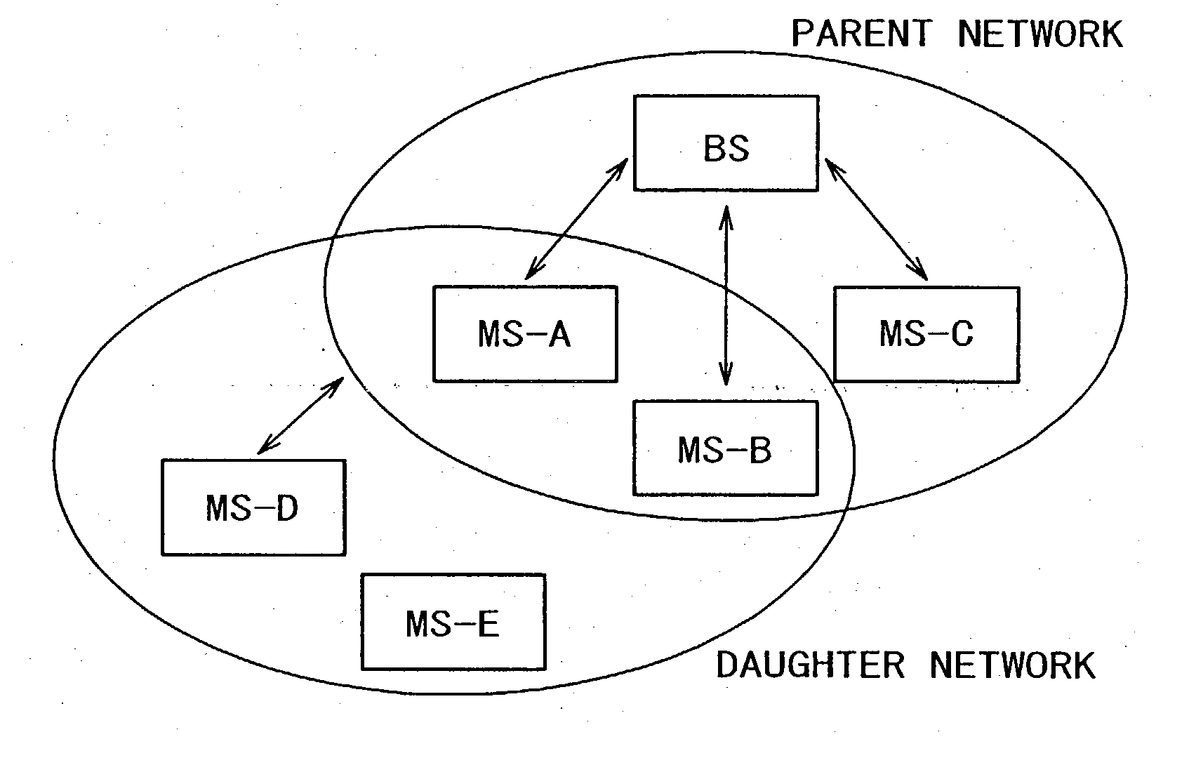
[0271] From above, from left

[0272] TDMA FRAME

[0273] PARENT NETWORK BEACON USER A USER B USER C CONTENTION PARTITION

[0274] DAUGHTER NETWORK BEACON USER D USER E CONTENTION PARTITION

[0275] FIG. 5

[0276] From left

[0277] FIRST PICONET 1

[0278] SECOND PICON...


PUM


Abstract

A communication terminal under the control of a wireless base station recursively has wireless base station capabilities in a parent network, constructs a daughter network within a scope of resources of the own apparatus assigned by the wireless base station, and assigns the resources to an other communication terminal under the control of the communication terminal having base station capabilities. This novel constitution allows to configure two or more networks guaranteed not to interfere each other, thereby allowing the coexistence of a plurality of personal area networks on a same frequency channel. At the same time, the novel constitution allows expanding a network area without increasing the scale of equipment.

Description

[0001] The present invention relates generally to a wireless communication system, a wireless communication control apparatus and a wireless communication control method, and a computer program which realize mutual communication between a plurality of wireless stations and, more particularly, to a wireless communication system, a wireless communication control apparatus and a wireless communication control method, and a computer program which realize the construction of a network under the control of a particular control station.[0002] To be more specific, the present invention relates generally to a wireless communication system in which a plurality of wireless networks exist at the same time, a wireless communication control apparatus and a wireless communication control method for controlling the communication operation in each of a plurality of contending wireless networks, and a computer program. Still more specific, the present invention relates to a wireless communication sys...

Claims


Application Information

Patent Timeline
Patent Type & Authority Applications(United States)
IPC IPC(8): H04L12/28H04W16/02H04W72/54H04W84/12H04W84/18H04W84/22H04W88/04
CPCH04L47/14H04W72/082H04W88/04H04W84/22H04W84/18H04W72/541H04L12/2801H04W8/04
Inventor SUZUKI, MITSUHIROSUGAYA, SHIGERU
Owner SONY CORP
Learn More