
Methods for vascular reconstruction of diseased arteries

a vascular reconstruction and diseased artery technology, applied in the field of diseased, nonaneurysmal arteries with vascular reconstruction, can solve the problems of arterial wall damage and injury, narrowing of the vessel and blood flow restriction, and difficulty in using this techniqu

Inactive Publication Date: 2003-08-28
TYCO HEALTHCARE GRP LP
View PDF46 Cites 48 Cited by
  • Summary
  • Abstract
  • Description
  • Claims
  • Application Information

AI Technical Summary

Problems solved by technology

The catheter is then passed through the lumen of the vessel until it reaches the stenoic region, which is characterized by a build up of fatty streaks, fibrous plaques and complicated lesions on the vessel wall, which result in a narrowing of the vessel and blood flow restriction.
Although PTCA has produced excellent results and low complication rates, there has, however, been difficulties associated with the use of this technique.
In particular, during the expansion of the balloon against the arterial wall, the arterial wall is frequently damaged and injured.
While this damage itself is not believed to be particularly harmful to the health or the life of the patient, the healing response triggered by this damage can cause a reoccurrence of the atherosclerotic condition.
However, it has been found that restenosis can still occur with such stents in place.

Method used


Image

  • Methods for vascular reconstruction of diseased arteries
  • Methods for vascular reconstruction of diseased arteries
  • Methods for vascular reconstruction of diseased arteries

Examples


example 1

[0174] The purpose of this example is to demonstrate the preparation of a fluid polymer composition useful in the methods of this invention.

[0175] Specifically, an EVOH polymer composition was prepared as follows:

[0176] Composition

[0177] A) 8 g EVOH (48 mole % ethylene);

[0178] B) 30 g tantalum having an average particle size of about 3 .mu.m (narrow size distribution); and

[0179] C) 100 mL DMSO (anhydrous).

[0180] Component A) was added to Component C) at 50.degree. C. and stirred for 2 hrs on a hot plate under an argon blanket. To this resulting composition was added Component B) and the resulting mixture was mixed until homogeneous.

example 2

[0181] The purpose of this example is to demonstrate the preparation of a fluid polymer composition useful in the methods of this invention.

[0182] Specifically, an EVOH polymer composition was prepared as follows:

[0183] Composition

[0184] A) 16 g EVOH (48 mole % ethylene);

[0185] B) 30 g tantalum having an average particle size of about 3 um (narrow size distribution); and

[0186] C) 100 mL DMSO (anhydrous).

[0187] Component A) was added to Component C) at 50.degree. C. and stirred for 3 hrs on a hot plate under an argon blanket. To this resulting composition was added Component B) and the resulting mixture was mixed until homogeneous.

example 3

Vascular Reconstruction of an H-Shaped Fistula

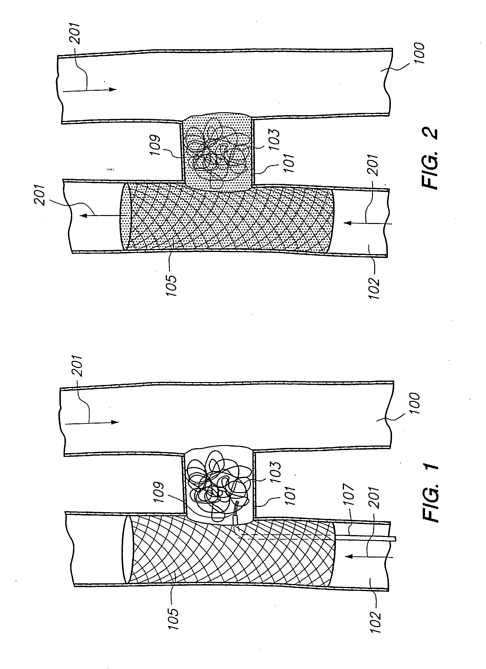
[0188] The purpose of this example is to demonstrate procedures which can be used to treat diseased, non-aneurysmal arteries with vascular reconstruction. In this example, vascular reconstruction of an H-Shaped Fistula is demonstrated.

[0189] As shown in FIG. 1, an H-Shaped Fistula has been identified for vascular reconstruction. Prior to vascular reconstruction, the vein (100), the fistula cavity (101) and the adjoining diseased artery (102) participate in the systemic blood flow (201) of the patient. Microcatheter techniques are used to deliver a mesh stent (105) to the diseased artery at the site of the desired vascular reconstruction. Such techniques can include, but are not limited to, (1) delivering a self-expanding stent to the vascular site, (2) delivering a stent and balloon catheter to the site and inflating the balloon to expand the stent or (3) triggering stent expansion by sliding back a sheath to release the stent. The mesh ...


PUM


Abstract

Disclosed are methods for vascular reconstruction of diseased, non-aneurysmal arteries.

Description

[0001] This application claims priority to U.S. Provisional Patent Application Serial No. 60 / 249,342, filed Nov. 15, 2000 and U.S. Provisional Patent Application Serial No. 60 / 252,757, filed Nov. 21, 2000, both of which are incorporated herein in their entirety.FIELD OF THE INVENTION[0002] This invention is directed to methods of treating diseased, non-aneurysmal arteries with vascular reconstruction.[0003] Specifically, the methods of this invention can be used to remodel blood flow pathways, redirect blood flow patterns, and to seal off undesired blood flow pathways. The methods of this invention can be used to treat a variety of diseased arteries in need of vascular reconstruction. For instance, the invention can be used to treat fistulas and other vascular abnormalities. In addition, the invention can be used to treat vascular walls which have suffered traumatic tears, punctures or dissections. The methods of this invention can also be used to treat or prevent stenosis in arteri...

Claims


Application Information

Patent Timeline
IPC IPC(8): A61B17/00A61B17/12A61F2/30A61F2/90
CPCA61B17/00491Y10S623/903A61B17/12109A61B17/12118A61B17/1214A61B17/12172A61B17/12186A61B2017/1205A61F2/07A61F2/90A61F2/945A61F2002/077A61F2002/30583A61F2210/0085A61B17/12022
Inventor WALLACE, GEORGEGREFF, RICHARD J.SLEE, EARL H.WHALEN, THOMAS J. II
Owner TYCO HEALTHCARE GRP LP
Learn More