Method for forming a thin film

a thin film and film technology, applied in the field of thin film forming, can solve the problems of large cost, complicated operation in use, and high energy condition, and achieve the effect of easy oxidation and short tim

Inactive Publication Date: 2003-08-21
TOKYO INST OF TECH
View PDF7 Cites 0 Cited by
  • Summary
  • Abstract
  • Description
  • Claims
  • Application Information

AI Technical Summary

Benefits of technology

0031] If an oxide thin film is formed on the anode electrode according to the thin film-forming method of the present invention, it is desired to incorporate an oxidizer in the reactive solutio...

Problems solved by technology

Therefore, those methods require large scale and complicate apparatus, resulting in large cost and complicate operationality ...

Method used


Image

  • Method for forming a thin film
  • Method for forming a thin film

Examples


Embodiment Construction

[0033] This invention will be concretely described with reference to the following examples.

[0034] First of all, a cobalt electrode as the anode electrode and a platinum electrode as the cathode electrode were set in a flow-type reactor.

[0035] Then, a reactive solution with an amount of 250 mL was made of distilled water and LiOH.H.sub.2O (4M) melted in the distilled water. The re-active solution was put in the flow-type reactor, and then, held at 150.degree. C. and flown in between the cobalt electrode and the platinum electrode at a flow rate of 5 mL / minute.

[0036] Then, a given voltage was applied between the electrodes so that a current density of 1 mA / cm.sup.3 was flown therebetween, and hydrogen peroxide (H.sub.2O.sub.2) was dropped off into the reactive solution at a rate of 1 mL / minute.

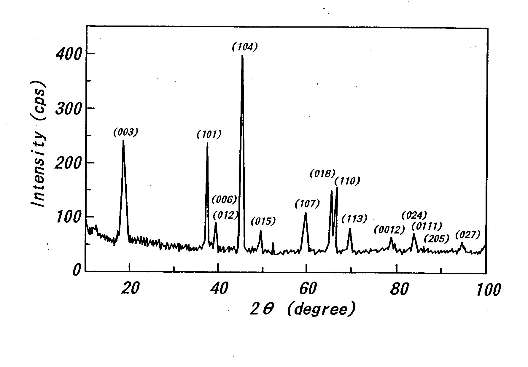
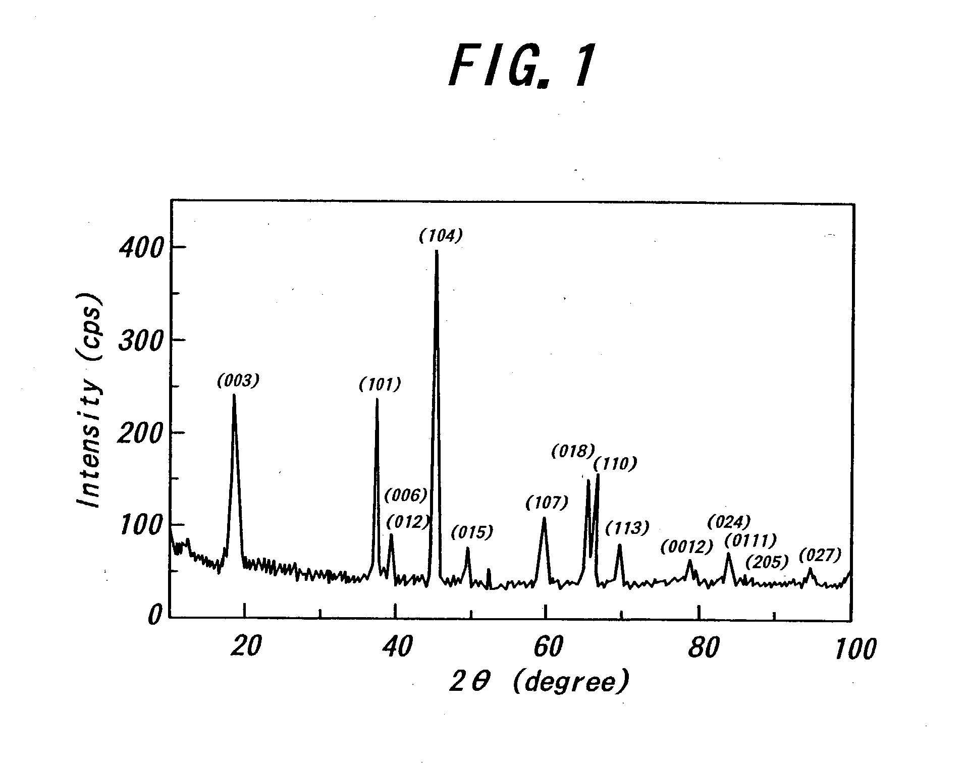
[0037] Three hours later, the cobalt electrode was taken out of the flow-type reactor, and the surface of the cobalt electrode was analyzed by X-ray diffraction. The thus obtained X-ray diffrac...


PUM

PropertyMeasurementUnit
Volumeaaaaaaaaaa
Temperatureaaaaaaaaaa
Flow rateaaaaaaaaaa

Abstract

A reactive solution with an amount of 250 mL is made of distilled water and LiOH.H2O (4M) melted in the distilled water. Then, the reactive solution is put in a flow-type reactor, and is flown in between an anode electrode and a cathode electrode set in the flow-type reactor at a given temperature and a given flow rate. Then, a given voltage is applied between the anode electrode and the cathode electrode with dropping an oxidizer of hydrogen peroxide (H2O2) into the reactive solution to form a lithium-cobalt oxide thin film on the anode electrode.

Description

[0001] 1. Field of the Invention[0002] This invention relates to a method for forming a thin film, particularly to a method for forming a thin film suitable for a secondary battery field usable for mobile electronic device and electric automobiles.[0003] 2. Related Art Statement[0004] So far, a sol-gel method, a CVD method or a PVD method is employed as a thin film-forming method. These methods require multistage process including a heating process, a high vacuum condition, or a high energy condition accompanied with a substrate-heating process or a plasma-generating process. Therefore, those methods require large scale and complicate apparatus, resulting in large cost and complicate operationality in use.[0005] Moreover, the above high energy condition runs counter to global environmental protection, resource saving and energy saving. Therefore, a new thin film-forming method without the above high energy condition has been desired.SUMMERY OF THE INVENTION[0006] It is an object of ...

Claims


Application Information

Patent Timeline
IPC IPC(8): C25D9/06C25D9/04H01M4/02H01M4/04H01M4/139H01M4/1391H01M4/52H01M4/525H01M6/40
CPCH01M4/0438H01M4/0452Y02E60/122H01M4/525H01M6/40H01M4/139Y02E60/10
Inventor YOSHIMURA, MASAHIROSONG, SEUNG-WANWATANABE, TOMOAKI
Owner TOKYO INST OF TECH
Why Eureka
Try Eureka