Optical assembly for rear projection television
- Summary
- Abstract
- Description
- Claims
- Application Information
AI Technical Summary
Benefits of technology
Problems solved by technology
Method used
Image
Examples
Embodiment Construction
[0016] A preferred embodiment of the present invention will be explained with reference to the accompanying drawings.
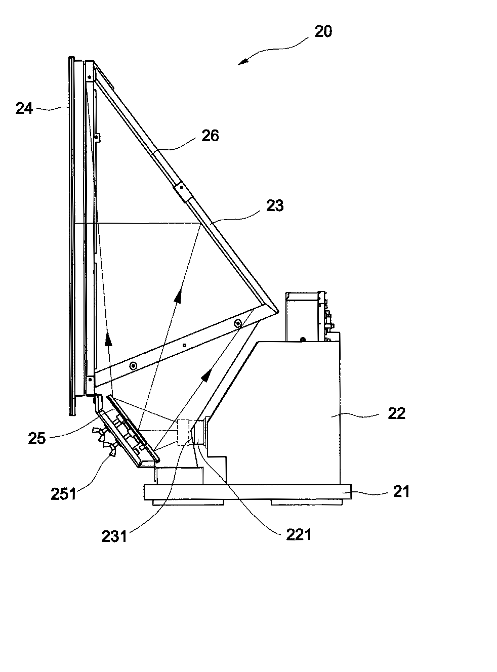
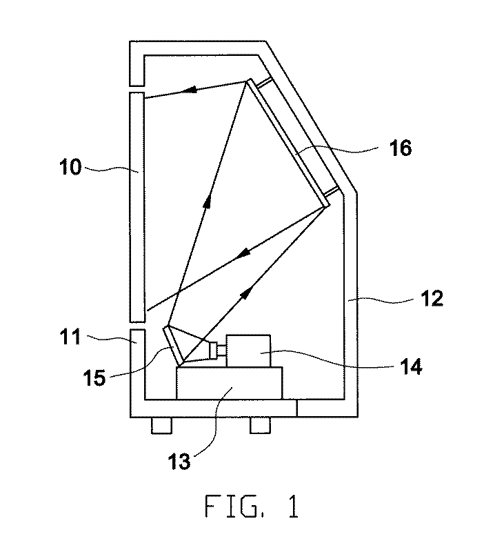
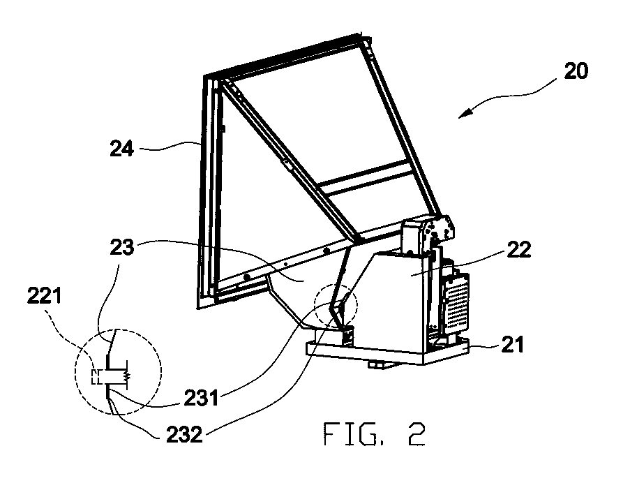
[0017] Please refer to Figure 2,the optical assembly for rear projection television, which comprises an optical assembly 20; an optical engine 22 disposed on the lower carrier 21 of the optical assembly 20; a hood member 23 coupled to an end of the carrier 21 in the front of the optical engine 22; an inlet 231 disposed on the hood member 23, the inlet 231 having an elastic sealed cover 232 which allows the projection lens 221 of the optical engine 22 to be extended into the hood member 23 and closely wraps the external diameter of the projection lens 221, and the hood member 23 is extended upward; a screen 24 is disposed at the outlet to constitute an independent structure of the optical assembly 20.
[0018] Please refer to Figure 3, the optical assembly for rear projection television, comprises an inlet 231 disposed at the bottom of the hood member 23 that enables the ...
PUM
 Abstract
Description
Claims
Application Information
 - R&D
- Intellectual Property
- Life Sciences
- Materials
- Tech Scout
- Unparalleled Data Quality
- Higher Quality Content
- 60% Fewer Hallucinations
Browse by: Latest US Patents, China's latest patents, Technical Efficacy Thesaurus, Application Domain, Technology Topic, Popular Technical Reports.
© 2025 PatSnap. All rights reserved.Legal|Privacy policy|Modern Slavery Act Transparency Statement|Sitemap|About US| Contact US: help@patsnap.com


