Semiconductor-on-insulator lateral p-i-n photodetector with a reflecting mirror and backside contact and method for forming the same
a technology of semiconductor and photodiode, which is applied in the field of photodetector for optical communication and to the method of forming a pin photodiode in a semiconductor, can solve the problems of high cost, high cost, and high cost, and achieve the effect of low cost, low quantum efficiency at 850 nm, and high efficiency
- Summary
- Abstract
- Description
- Claims
- Application Information
AI Technical Summary
Problems solved by technology
Method used
Image
Examples
embodiment
Preferred Embodiment
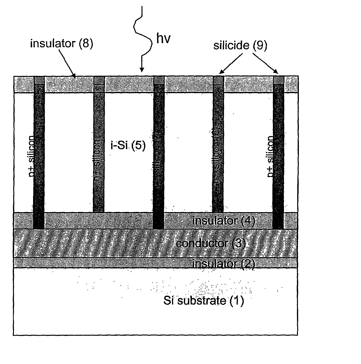
[0050] FIG. 3A illustrates a cross section of a structure according to the present invention which includes a silicon substrate 1, a first insulator layer 2 such as oxide, a conductor film 3 such as tungsten (or other metals such as refractory metals that withstand the bonding anneal) or heavily doped poly-Si, a second insulator film 4, an intrinsic silicon-on-insulator layer 5, and alternating n-type 6 and p-type 7 filled trenches.
[0051] The contacts to the n-type trenches 6 are made on the top surface, whereas contacts to the p-type trenches 7 are made to the top and to the bottom of each trench 7.
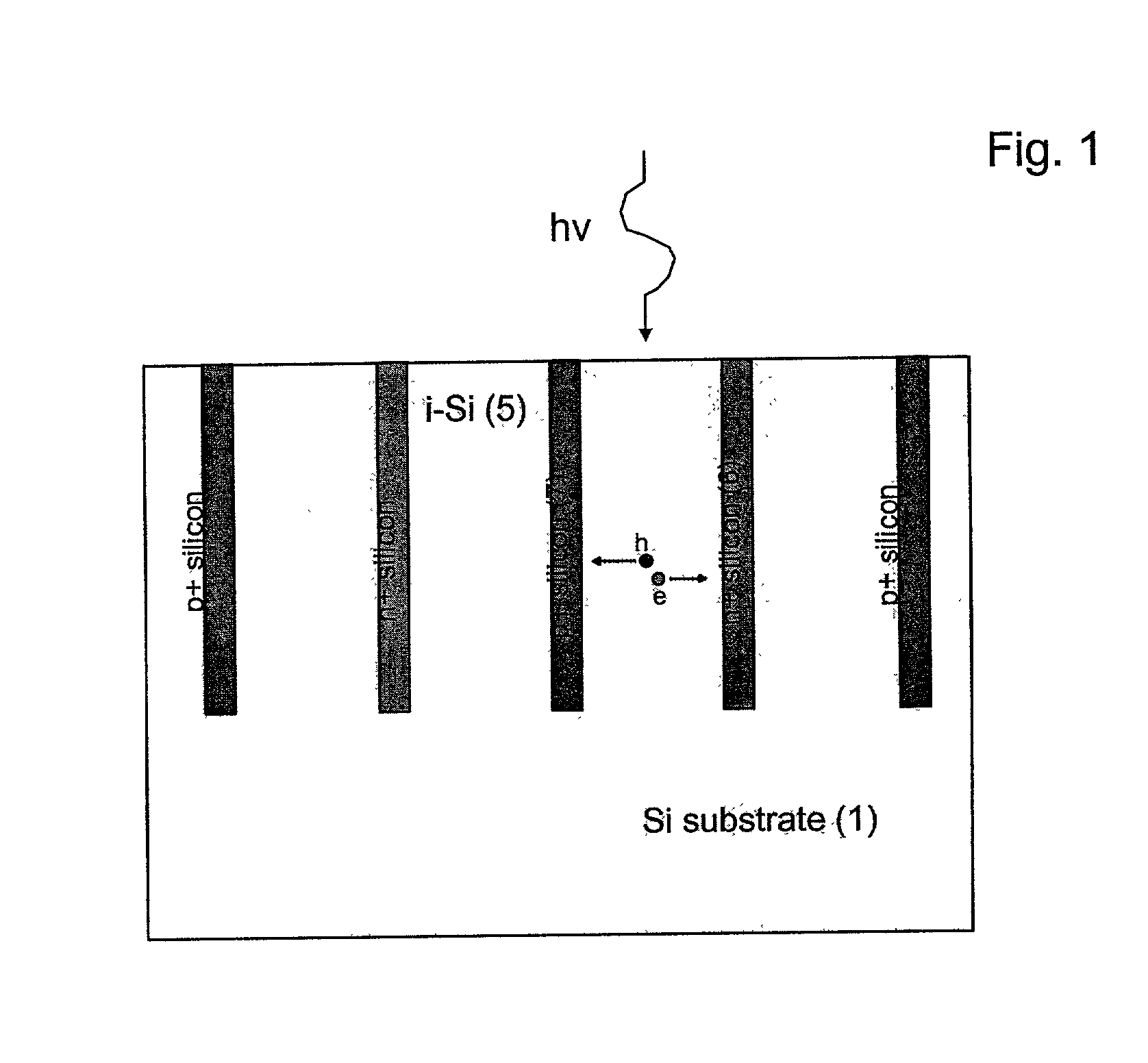
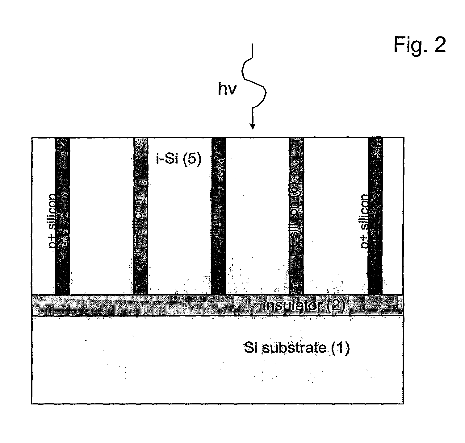
[0052] A top view of the detector layout is shown in FIG. 4. The top portion of each trench is converted into silicide 9, such as CoSi.sub.2, to minimize the series resistance from the metal pad 10 to the trench. Such a structure has several advantages over the conventional structures described above and shown in FIGS. 1 and 2.
[0053] For example, a sandwich structure,...
second embodiment
[0064] Turning now to FIG. 3D, the present inventors have found that it is desirable to roughen the silicon 5-insulator 4 interface so that the buried mirror 30 (e.g., formed by insulator 4, conductor 3, and insulator 2) is diffusive.
[0065] There are several advantages of the diffusive mirror 30 including that a portion of the impinging light would be reflected back into the detector at angles other than perpendicular to the detector surface. Thus, the light's second pass would be longer than the trench depth by 1 / cos(.theta.), where .theta. is the angle by which they diverge from the normal to the surface. If the angle of reflection is large enough, then the light would not escape the silicon film 5 due to total internal reflection.
[0066] The configuration of a silicon film 5 on top of a flat mirror will exhibit an etalon effect, such that a destructive interference will result for some wavelengths. Avoiding those dips in the spectrum may be difficult if the silicon film is thick a...
third embodiment
[0076] FIG. 5 illustrates a cross-section of another trench photodetector 50 embodiment. Photodetector 50 has the following additional features.
[0077] That is, the detector 50 is back-illuminated and thus does not require a backside mirror. Instead, a mirror 12 is fabricated (deposited) on top of the wafer surface, which simplifies the fabrication process, since complex mirror bonding steps can be avoided. Mirror 12 may be a metallic mirror or a dielectric mirror which is formed of a multi-layer stack. Such a stack may be formed, for example, from alternating layers of two materials having very different indices of refraction (e.g., polysilicon and oxide, or a nitride and an oxide). The thickness of such layers should be carefully selected since the mirror (unlike a conductor mirror which operates for almost any wavelength) should be tailored to the wavelength of operation.
[0078] For example, as shown in FIG. 9, the dielectric mirror can be tailored to be very reflective at 850 nm (...
PUM
 Abstract
Description
Claims
Application Information
 - R&D
- Intellectual Property
- Life Sciences
- Materials
- Tech Scout
- Unparalleled Data Quality
- Higher Quality Content
- 60% Fewer Hallucinations
Browse by: Latest US Patents, China's latest patents, Technical Efficacy Thesaurus, Application Domain, Technology Topic, Popular Technical Reports.
© 2025 PatSnap. All rights reserved.Legal|Privacy policy|Modern Slavery Act Transparency Statement|Sitemap|About US| Contact US: help@patsnap.com


