
Advanced control strategies for chlorine dioxide generating processes

a technology of chlorine dioxide and control strategies, applied in the direction of electric controllers, instruments, ignition automatic control, etc., can solve the problems of difficult control of these variables using conventional control strategies, and the possibility of on-line instruments, so as to improve the quality of bleached pulp products, reduce chemical costs, and reduce the loading of biological oxygen demand (bod) through methanol consumption

Inactive Publication Date: 2003-06-26
SUPERIOR PLUS INCOME FUND +2
View PDF10 Cites 15 Cited by
  • Summary
  • Abstract
  • Description
  • Claims
  • Application Information

AI Technical Summary

Benefits of technology

[0057] In the present invention, the full scope of chlorine dioxide generating plant operation can be monitored and controlled automatically by a computer programmed by software effecting the various monitoring and calculations. The chlorine dioxide production rate is the sole input variable required to be provided by the plant operator to the system. At times, due to various reasons, the plant may not produce the amount of chlorine dioxide expected from given flows of chemicals. The control system provided herein rapidly determines the degree of production rate deviation and makes the required adjustments to the methanol feed set point to maintain the desired production rate. Not only does the control system optimize steady state chlorine dioxide generating plant operations but also transitions between desired production rates, with continued stable operation. Stable generator level control at steady state, for example, .+-.1%, is achieved by the synergistic use of steam and make-up water. Water load and steam usage are minimized.

Problems solved by technology

Unfortunately, a viable on-line instrument to measure these key control variables is not commercially available and hence presently, an operator must rely upon the results of manual laboratory tests, performed usually at two hours intervals, to guide him in making adjustments to the manipulated variables (i.e. acid and chlorate feed rates) to maintain chlorine dioxide production at the desired level.
The control is further complicated by fluctuations in generator liquor level that result in the generator liquor species either concentrating or diluting in the intervals between laboratory tests and thus it is difficult to control these variables using conventional control strategies.

Method used


Image

  • Advanced control strategies for chlorine dioxide generating processes
  • Advanced control strategies for chlorine dioxide generating processes
  • Advanced control strategies for chlorine dioxide generating processes

Examples


example

[0136] This Example illustrates the application of the present invention to chlorine dioxide generation plant.

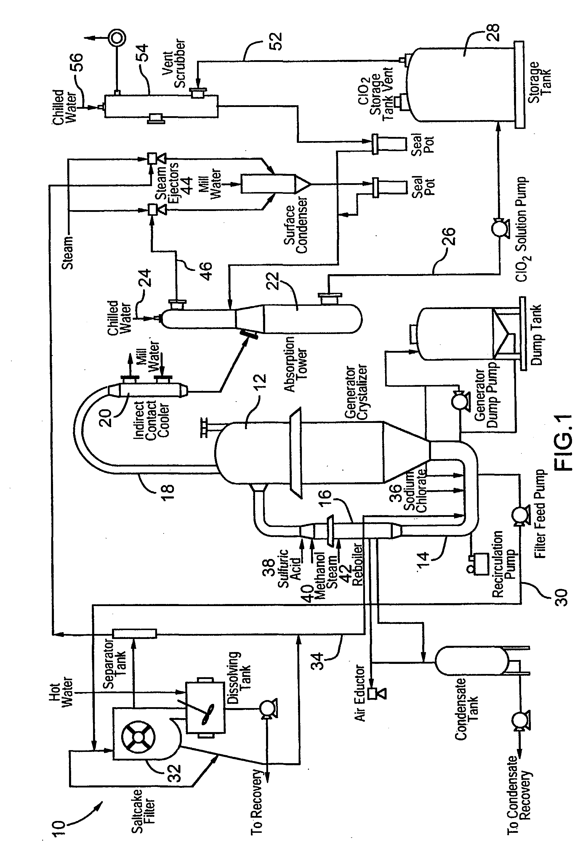
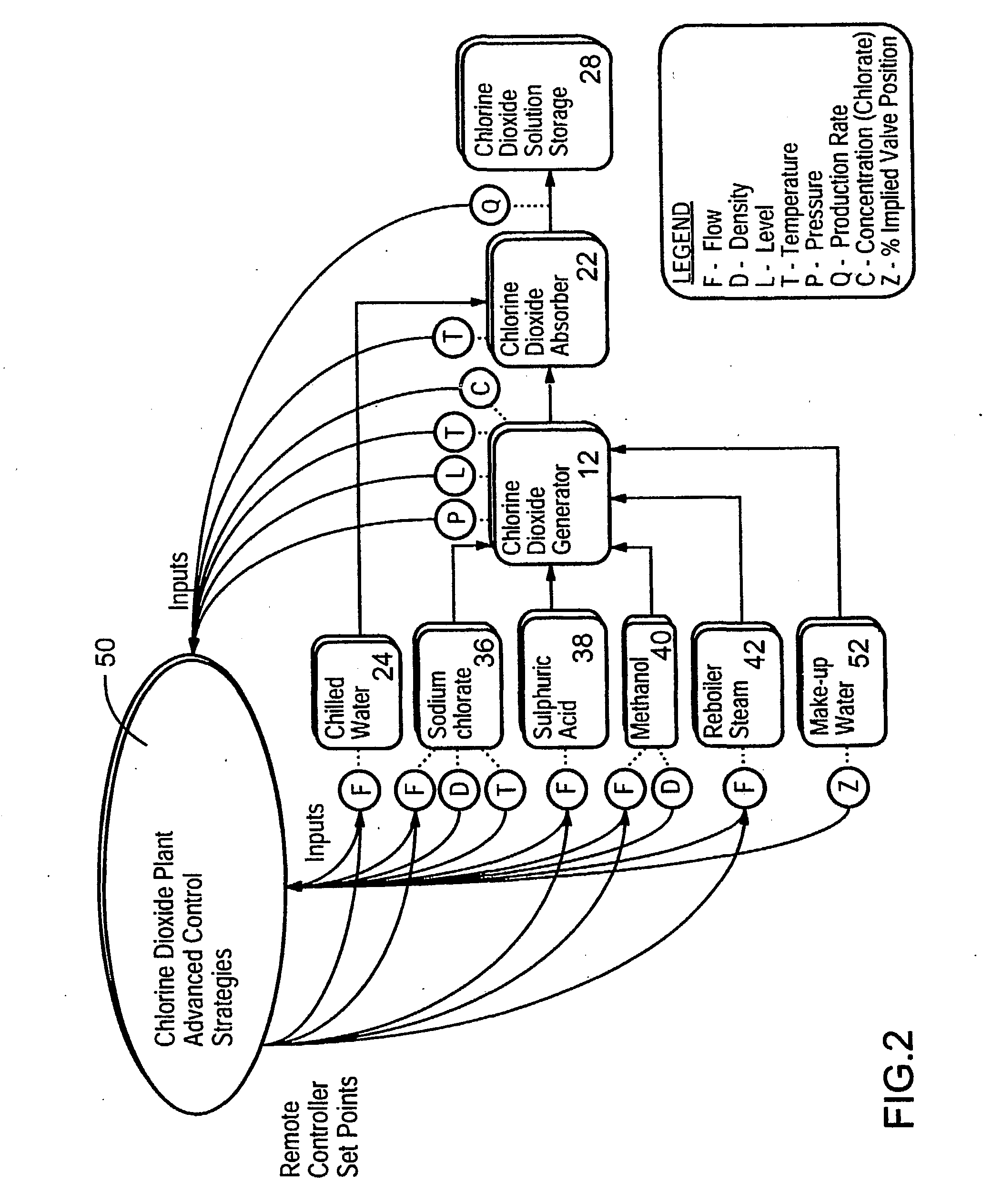
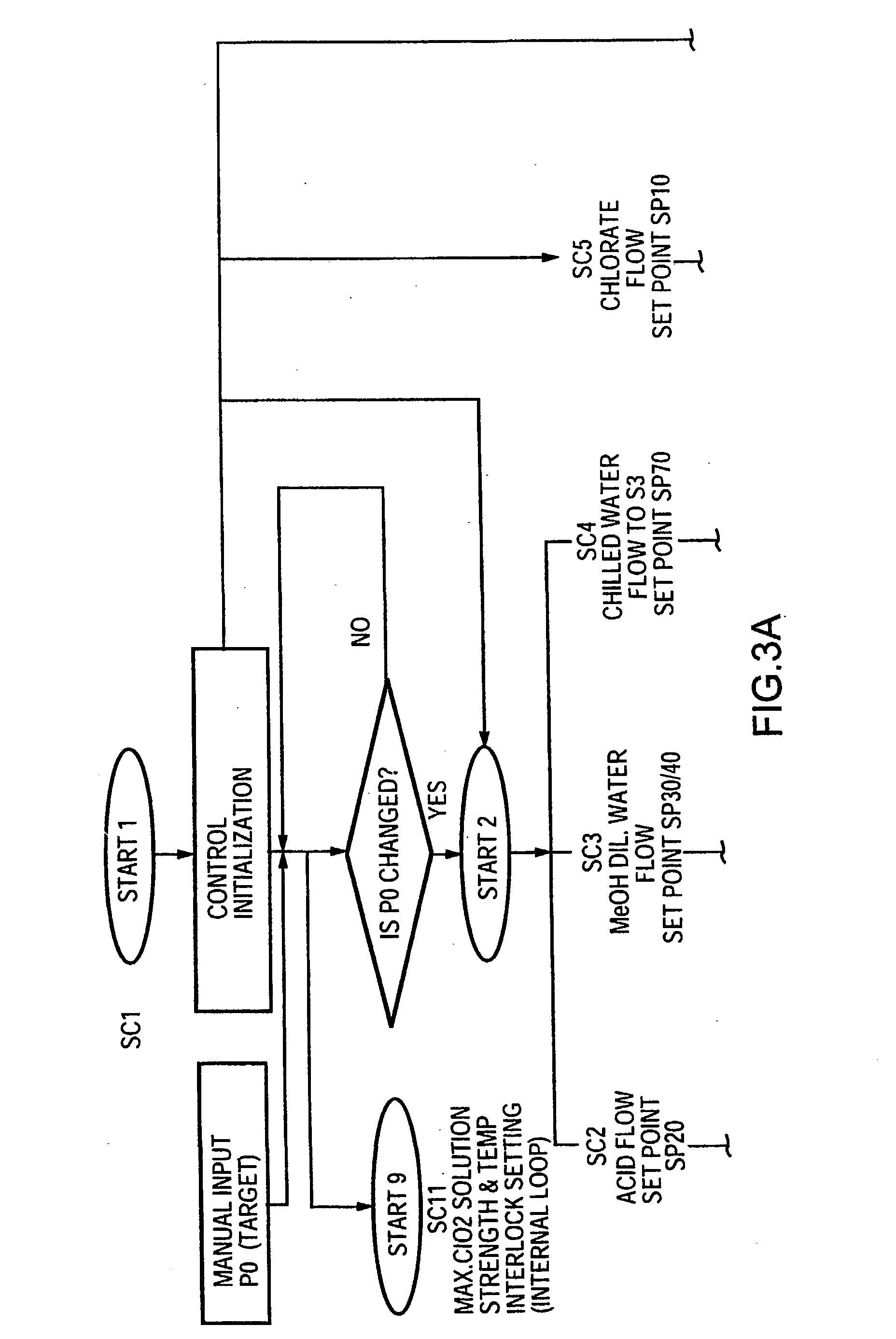
[0137] A commercial chlorine dioxide generating plant according to FIG. 1 was operated both conventionally and by utilizing the control system described herein and shown in FIGS. 2 to 13B.

[0138] In this plant scale study over a period of 12 months, the control system described herein in comparison to conventional operation resulted in an increase in yield of chlorine dioxide based on chlorate of over 2% and a significantly-decreased requirement for lab testing.

[0139] In addition, reductions were achieved in the variability of certain chlorine dioxide generator process parameters, as set forth in the following Table:

2TABLE % Variability Parameter Reduction Deviation from Chlorine Dioxide Production Target 82% Deviation from Chlorine Dioxide Strength Target 37% Chlorine Dioxide Solution Strength to Bleach Plant 35% Generator Level 35% Acid Normality in Generator Liquor 8% Chlo...


PUM

PropertyMeasurementUnit
concentrationaaaaaaaaaa
boiling pointaaaaaaaaaa
flow ratesaaaaaaaaaa

Abstract

Chlorine dioxide generating processes of the single vessel type which produce chlorine dioxide of high purity are monitored and controlled by a computer using Advanced Control Strategies for steady, stable operation with optimum chemical usage on the basis of a desired chlorine dioxide production rate as the sole input from an operator to the computer program effecting the computer control.

Description

[0001] The present invention relates to the generation of chlorine dioxide, particularly for pulp bleaching and, specifically, the control of such process.BACKGROUND TO THE INVENTION[0002] Chlorine dioxide is produced commercially on site at a pulp mill for use as a bleaching agent for the pulp. A variety of procedures have been described in the prior art and have been used commercially. In general, the process proceeds in accordance with the equation:ClO.sub.3.sup.-+Cl.sup.-+2H.sup.+.fwdarw.ClO.sub.2+1 / 2Cl.sub.2+H.sub.2O[0003] One common procedure involves the so-called single vessel process (SVP), in which chlorine dioxide is formed from an aqueous acid reaction medium, or generator liquor, which is maintained at its boiling point in a reaction zone under a subatmospheric pressure. Chlorine dioxide is removed from the generator in gaseous admixture with water vapour and is absorbed into chilled water in an absorption tower while by-product salt from the process precipitates in the...

Claims


Application Information

Patent Timeline
Patent Type & Authority Applications(United States)
IPC IPC(8): C01B11/02G05B15/02
CPCC01B11/023Y10T436/19G05B15/02
Inventor PU, CHUNMINBIRKS, JOHN BRIANHOPMANS, JAMES JOHANNES
Owner SUPERIOR PLUS INCOME FUND
Learn More