Internal combustion engine adjusting the rotation angle of a camshaft with respect to a crankshaft
a technology of internal combustion engine and camshaft, which is applied in the direction of valve arrangement, yielding coupling, coupling, etc., can solve problems such as damage to the internal combustion engin
- Summary
- Abstract
- Description
- Claims
- Application Information
AI Technical Summary
Benefits of technology
Problems solved by technology
Method used
Image
Examples
first embodiment
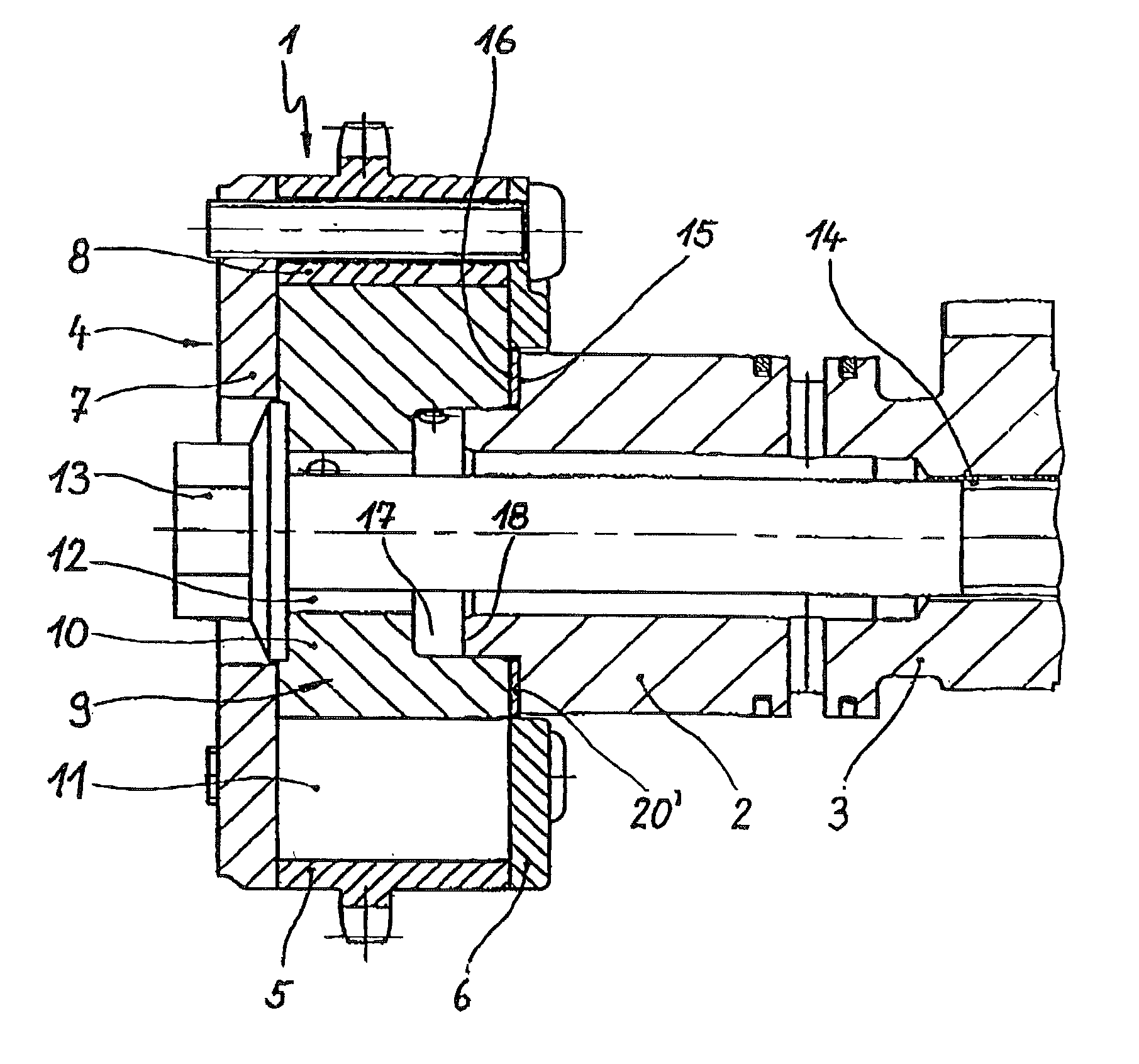
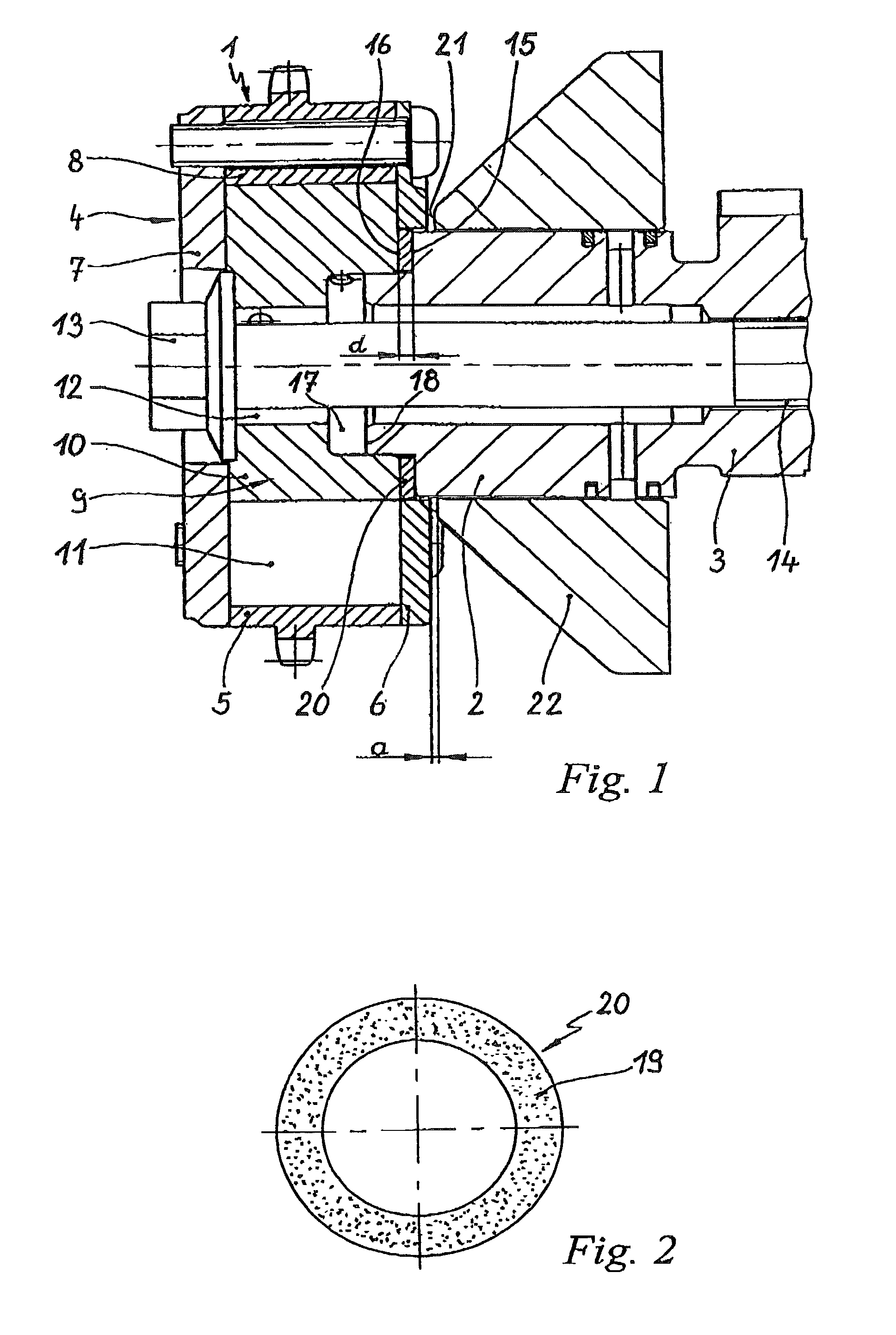
[0022] In FIGS. 1 and 2, the additional annular disk 20, comprises a metal disk which is coated on both opposite side faces with aluminum-titanium dioxide. The disk is inserted like a standard washer into the clamping joint between the output unit 9 of the device 1 and the end side 15 of the device 3. As a check that this annular disk 20 is present, the disk has a defined thickness d, while a stop face 21 is arranged opposite the drive unit 4 of the device 1, at a distance a which is selected to be less than the thickness d of the annular disk 20, in the direction which faces the camshaft. The stop face is defined by a further engine component 22, which in FIG. 1 is a pressure-medium distributor of the device 1. When the device 1 is being bolted to the camshaft 3 by the central securing bolt 13, unintentional omission of the annular disk 20 may be mechanically detected when the device 1 becomes jammed against the stop face 21.
second embodiment
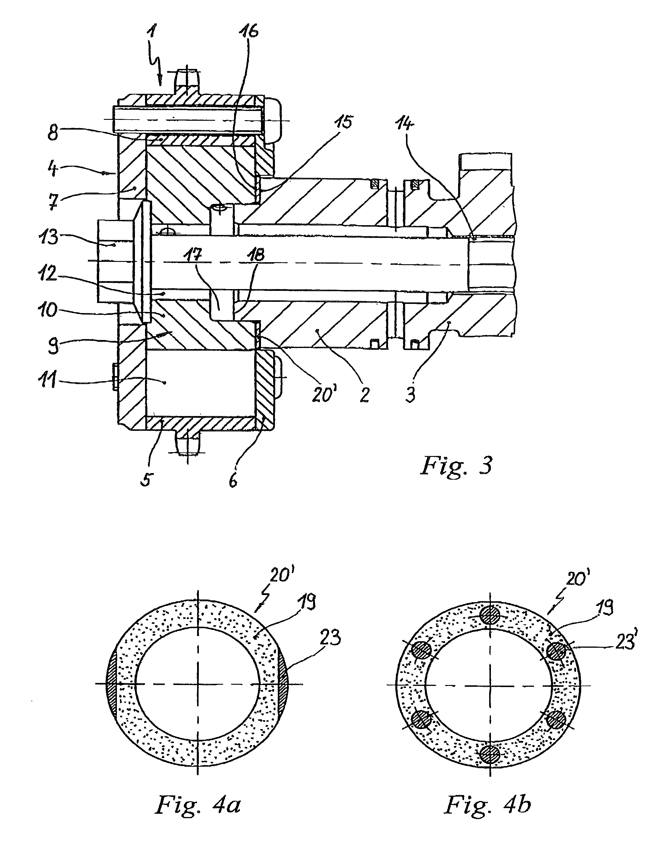
[0023] In the device 1 in FIG. 3, an additional annular disk 20' in FIG. 4a or 4b, comprises a plastic film or metal foil with a coating 19 comprised of diamond dust disposed on both opposite side faces. To check if this annular disk 20' is present when the device 1 is being bolted to the camshaft 3, the annular disk 20' has various visually detectable features, which make it stand out from adjacent components or make it visually noticeable. In the first annular disk 20' variant in FIG. 4a, these exemplary visual features are a reflection layer mixed into the coating 19 and recesses 23 machined into the side faces shaped as parallel notches. In the second annular disk 20' variant FIG. 4b, the optical features are an indicator color, which is mixed into the coating 19, and a plurality of recesses 23', which are machined into the side faces in the form of stamped holes distributed uniformly around the circumference. Through the recesses 23', as for the recesses 23 in the first disk va...
PUM
 Abstract
Description
Claims
Application Information
 - R&D
- Intellectual Property
- Life Sciences
- Materials
- Tech Scout
- Unparalleled Data Quality
- Higher Quality Content
- 60% Fewer Hallucinations
Browse by: Latest US Patents, China's latest patents, Technical Efficacy Thesaurus, Application Domain, Technology Topic, Popular Technical Reports.
© 2025 PatSnap. All rights reserved.Legal|Privacy policy|Modern Slavery Act Transparency Statement|Sitemap|About US| Contact US: help@patsnap.com


