Eureka AIR delivers breakthrough ideas for toughest innovation challenges, trusted by R&D personnel around the world.

Self-sealing electrical cable having a finned or ribbed structure between protective layers

a technology of electrical cables and protective layers, which is applied in the direction of cables, insulated conductors, conductors, etc., can solve the problems of not being able to meet the most difficult cables on the market today will not always stand up to the rigors of handling, installation and operation, etc., and achieves the effect of not being able to introduce a sealant into such spaces and not being entirely satisfactory

Inactive Publication Date: 2003-04-03
SOUTHWIRE CO LLC
View PDF18 Cites 15 Cited by
  • Summary
  • Abstract
  • Description
  • Claims
  • Application Information

AI Technical Summary

Problems solved by technology

The toughest cables on the market today will not always stand up to the rigors of handling, installation, and operation.
And exposed aluminum will eventually deteriorate.
However, it has been found that the mere introduction of a sealant into such spaces is not entirely satisfactory.
Attempts to prevent moisture from reaching the conductor, such as using water swellable material, have not met with technical and / or economic success.
For example, voids may be formed in the sealant during the application thereof or may be formed if the cable is accidentally punctured.
Any such spaces or voids form locations for the ingress of moisture which can lead to corrosion of the conductor and conventional sealants used in the cables cannot eliminate such voids.
The drawback to this method is that even though some deformation of the individual wires does take place, and some of the interstitial spacing is filled, there is still the possibility of cable insulation damage through which moisture can enter the cable and contact the conductor.
The problems encountered in applying such a filling substance revolve around precise metering of the material into the interstitial spaces as the stranded conductor is being formed.
If too much material is extruded into the conductor, the outer insulation will not fit properly.
Another drawback to this method of applying a moisture blocking material is that an extrusion head and an extrusion pump for applying the material is required for every individual layer of wires used to form the conductor.
The problems described above regarding the regulation of the volume of material applied through an extrusion head are multiplied every time an additional extrusion pump and extrusion head is required within the conductor manufacturing system.
Prior art efforts to manufacture an acceptable moisture blocked conductor revolved around methods for uniform application of the moisture blocking material to the conductor, but did not solve the problems created by handling and installation damage.
The disadvantages experienced here involve the practice of stranding the conductor beneath the surface of an elevated temperature moisture block pool.
No access, either visual or mechanical, to the conductor manufacturing process is practical.
The disadvantages here comprise a complex manufacturing line whereby moisture blocking material is applied at many different locations, each having to be meticulously monitored and controlled in order for a proper conductor construction to be obtained.
It can be readily seen from the above referenced methods and apparatuses that moisture blocked conductors are known and it can also be recognized that there are major problems concerning the elimination of moisture contacting the conductor as a result of handling and installation of a cable.
The sealant must not be applied too cold or it will prevent even distribution of the sealant in the fins or cause fin damage.

Method used


Image

  • Self-sealing electrical cable having a finned or ribbed structure between protective layers
  • Self-sealing electrical cable having a finned or ribbed structure between protective layers
  • Self-sealing electrical cable having a finned or ribbed structure between protective layers

Examples


example 1

[0071] This test was designed to evaluate the performance of the present invention's self sealing, 600 V underground cable. The test program was patterned after a previously developed procedure to evaluate self-sealing or self-repairing cable designs.

[0072] To conduct the test damaged cables were placed in a specially mixed, moist soil. The cables were then energized with 120 V ac to ground. Measurements made included changes in leakage current to earth and cable conductor resistance. The temperature of each cable near the damage point was also monitored.

[0073] Four control sample replicates and eight self-sealing sample replicates were evaluated. All four control samples failed the test relatively early in the test program. All eight self-sealing samples performed well, with no significant increase in conductor resistance and low leakage current values throughout the 60-day test period.

[0074] Conventional and self-sealing 600 volt underground cable with a 2 / 0 AWG combination unilay...

example 2

[0112] A cyclic load test was run on the finned cable of the present invention and compared with similar non-finned prior art cables. 50 ft. samples were tested. The samples had a 50.degree. C. conductor temperature, and were cycled on 8 hours a day and off 16 hours, 7 days a week. The cables were terminated with a mechanical connector. No duct seal, mastic tape, electrical tape, or the like was used. The tops of the samples were approx. 11 ft. above the floor. The samples gradually droop to the floor.

2SAMPLE 1 (Invention) Shrinkback Shrinkback Total Weeks of Aging at Top at Bottom Shrinkback (in) Initial .0000 .0000 .0000 1 .3035 .1510 .4545

[0113]

3SAMPLE 2 (Invention) Shrinkback Shrinkback Total Weeks of Aging at Top at Bottom Shrinkback (in) Initial .0000 .0000 .0000 1 .1385 .1880 .3265

[0114]

4SAMPLE 1 Bare (Prior Art) Shrinkback Shrinkback Total Weeks of Aging at Top at Bottom Shrinkback (in) Initial .8450 .2220 1.0670 1 4.6375 1.2010 5.8385 2 5.5390 .8220 6.3610 3 5.9350 .6735 6....


PUM

PropertyMeasurementUnit
Fractionaaaaaaaaaa
Angleaaaaaaaaaa
Massaaaaaaaaaa

Abstract

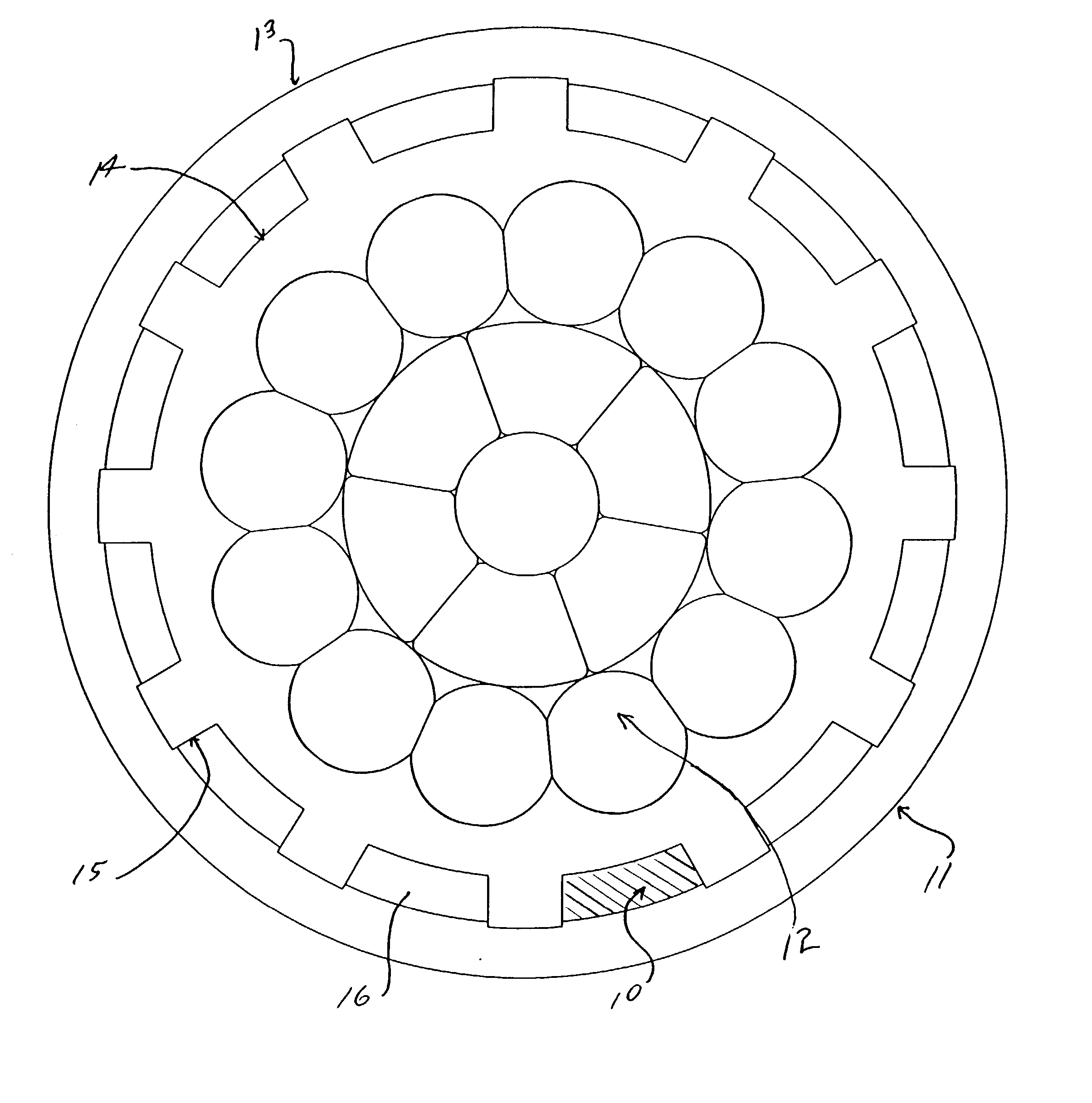
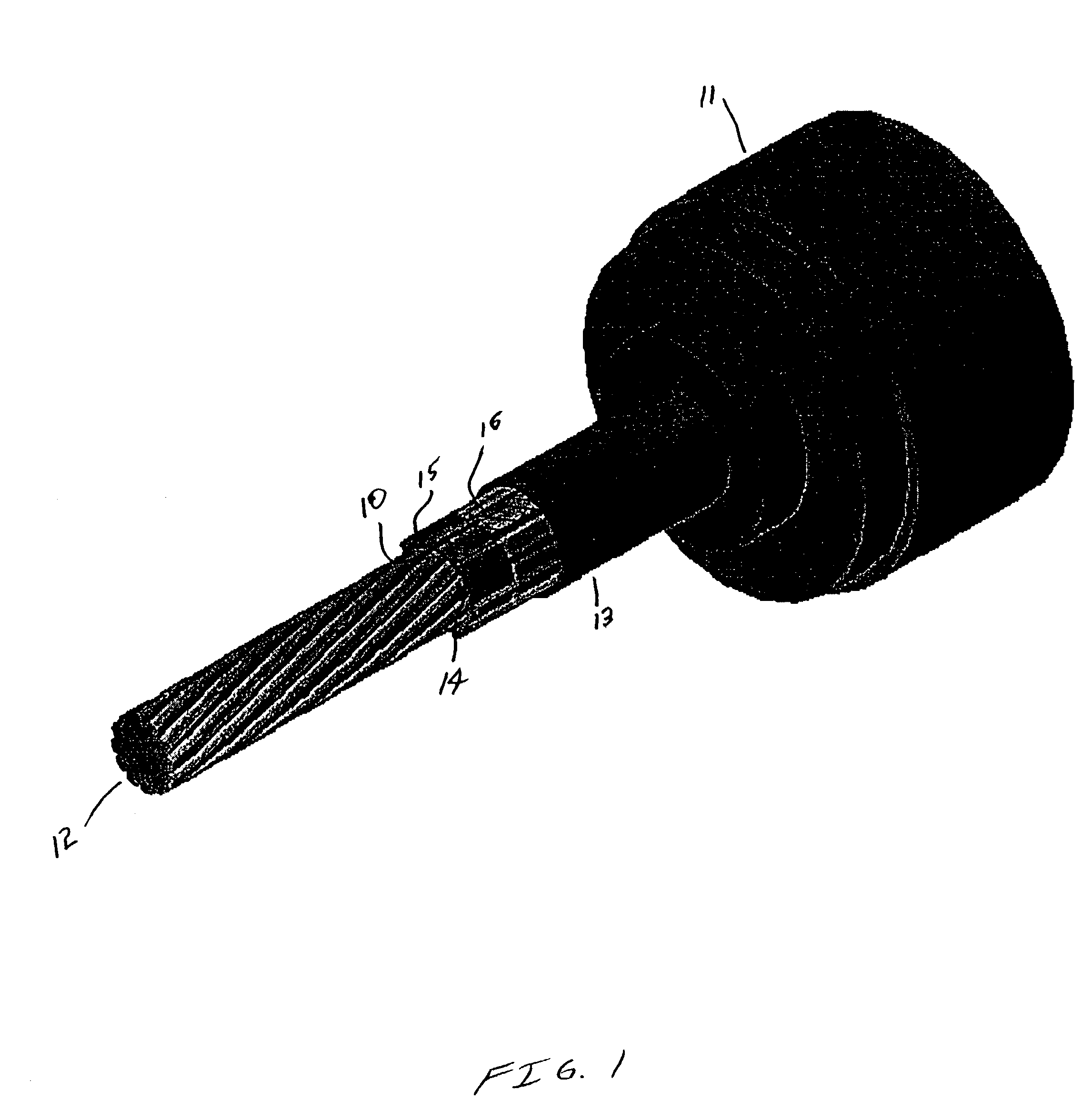
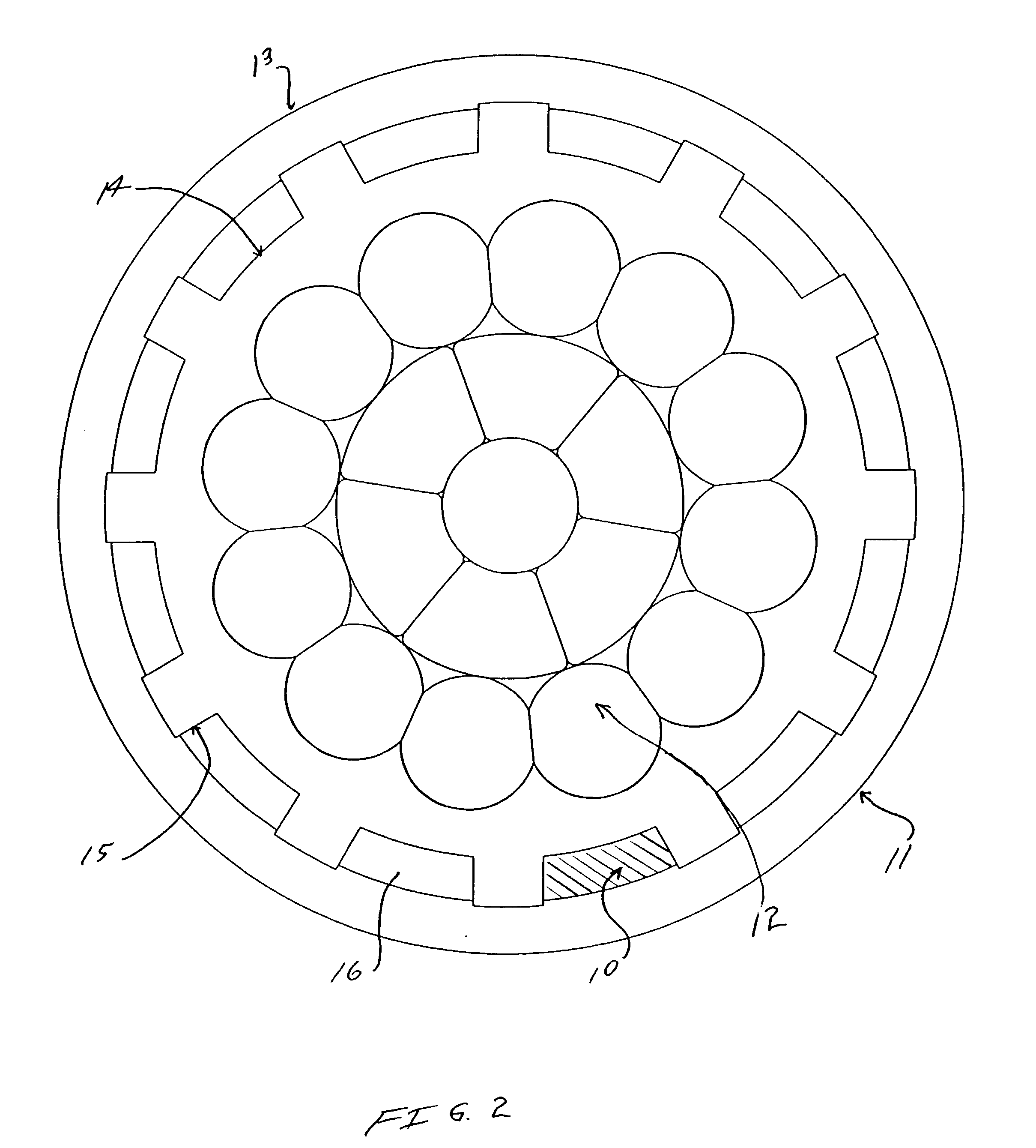
An electrical cable and a method for manufacturing the electrical cable are provided in which a plurality of insulated conductors have an inner protective layer extruded thereabout. A plurality of longitudinally extending ribs or fins or exterior ribbed or finned surfaces are formed outward of the inner protective layer between which exist a plurality of voids. An outer insulation layer can be formed in the same operation as the fins or ribbed surface and the inner layer or in a subsequent operation.

Description

[0001] This application is a continuation-in-part of patent application Ser. No. 09 / 730,661 filed Dec. 6, 2000 which is a continuation-in-part of patent application Ser. No. 09 / 756,533 filed Jan. 8, 2001, which is a division of patent application Ser. No. 09 / 228,482 filed Jan. 11, 1999, now U.S. Pat. No. 6,184,473 which is relied on and incorporated by reference.[0002] Insulated solid and stranded electrical cables are well known in the art. Generally stranded cables include a central stranded conductor with a protecting insulation jacket disposed around the conductor.[0003] The most frequent cause of failure of directly buried aluminum secondary cables is a cut or puncture in the insulation inflicted during or after installation. This leads to alternating current corrosion of the aluminum and finally to an open circuit. When a conductor is exposed to wet soil, upon damage, leakage current may flow, and cause localized electrochemical conversion of aluminum to hydrated aluminum oxid...

Claims


Application Information

Patent Timeline
IPC IPC(8): H01B7/18H01B7/282
CPCH01B7/184H01B7/2825H01B7/185Y02A30/14
Inventor WARE, JOHN NICHOLASSPRUELL, STEPHEN LEE
Owner SOUTHWIRE CO LLC
Why Eureka
Eureka Blog
Learn More