Gaseous-based radiation detector

a technology of ionizing radiation and detectors, which is applied in the field of gaseous-based ionizing radiation detectors, can solve the problems of inacceptability, large and bulky detectors, and harm to detectors, and achieves the effects of reducing the cost of detectors, and reducing the cost of ionizing radiation detection

Inactive Publication Date: 2003-03-20
XCOUNTER
View PDF5 Cites 6 Cited by
  • Summary
  • Abstract
  • Description
  • Claims
  • Application Information

AI Technical Summary

Problems solved by technology

Due to the strong electric fields created in the gaseous-based ionizing radiation detector, however, spark discharges can occur in the gas, and these can block the detector for a period of time, and can also be harmful for the detector and particularly for electronics thereof.
The longer the distance d.sub.1 is, the better spark discharge protection is obtained, but to the cost of large and bulky detectors.
In some applications this is not acceptable.
However, a structure of such kind having an effective protection against the occurrence of sparks would be difficult and / or expensive to manufacture.

Method used


Image

  • Gaseous-based radiation detector
  • Gaseous-based radiation detector
  • Gaseous-based radiation detector

Examples


first embodiment

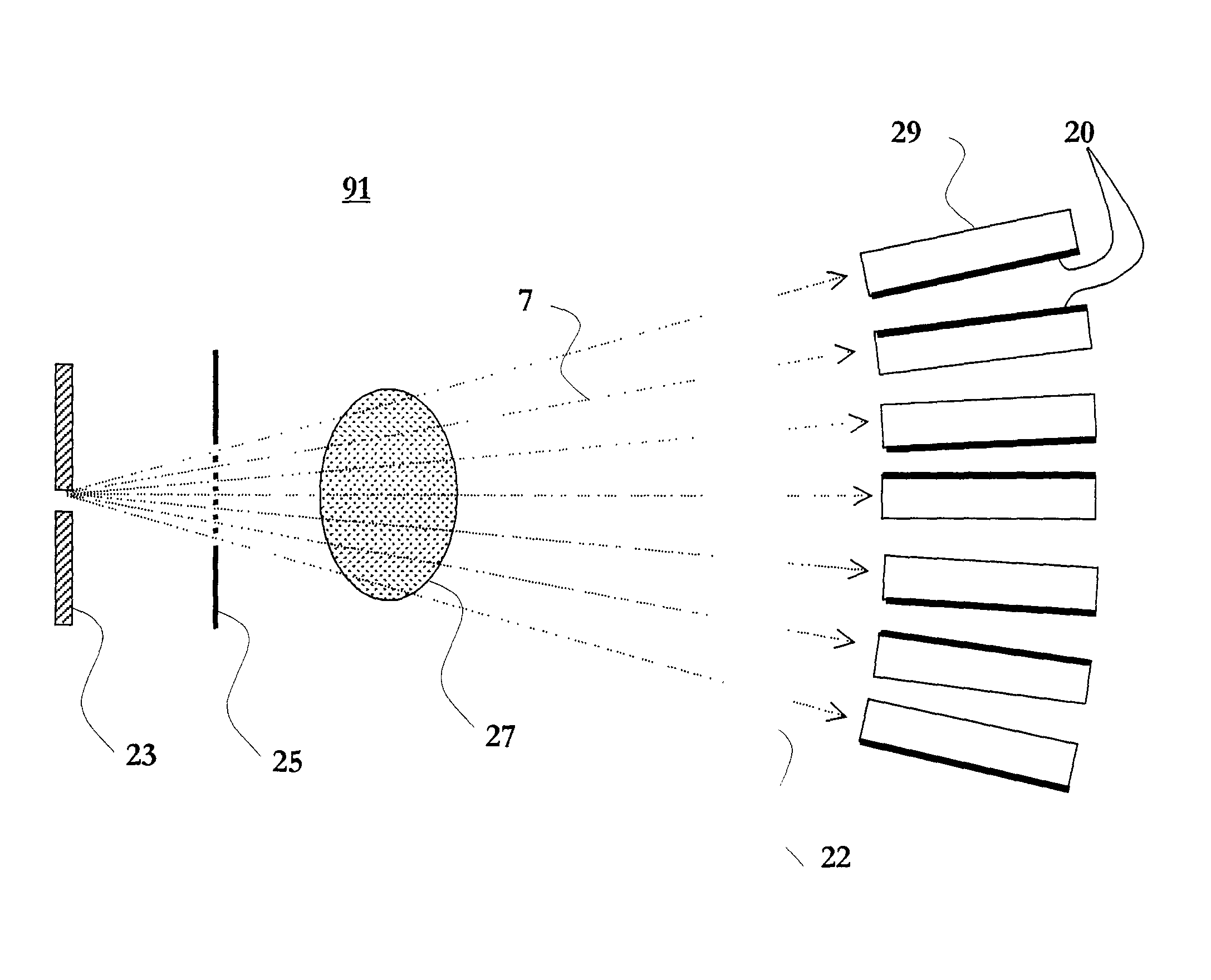
[0021] FIG. 2 is a front view of an end portion of a detector for planar beam radiography according to the present invention.

[0022] The detector is oriented such that a planar X-ray beam can enter sideways between a cathode arrangement 11, 12 and an anode arrangement 13, 14. A radiation transparent slit window (schematically indicated by dashed line 10), and optionally a collimator window (not illustrated) are provided at the front of the detector to form an entrance for the X-ray beam to the detector.

[0023] Each of the electrode arrangements includes an electrically conducting electrode layer 11, 13 supported by a respective dielectric substrate 12, 14, wherein the arrangements are oriented such that the cathode 11 and anode 13 layers are facing each other.

[0024] Preferably, the electrode arrangements 11, 12 and 13, 14 are planar, rectangular and parallel to each other. However, other geometries may be employed.

[0025] The electrode arrangements are separated by a spacer or support ...

second embodiment

[0038] Turning now to FIG. 3, which schematically illustrates in a front view a portion of a modified radiation detector the present invention will shortly be depicted.

[0039] This detector differs from the FIG. 2 detector only in that a further electrically conducting layer 21 is arranged on a surface of the dielectric anode substrate 14, which is opposite to the surface that carries the anode layer 12. The electrically conducting layer 21 is as layer 20 grounded, and this affects the electric field particularly within the dielectric anode substrate 14, see the illustrated electric field lines in FIG. 3. The electric field within the inter-electrode space close to the spacer 16 is similar to the one in FIG. 2.

third embodiment

[0040] In FIG. 4 is schematically illustrated in a front view a portion of yet a modified radiation detector and this third embodiment of the detector differs from the FIG. 2 embodiment only as regards the extension of the electrically conducting layer 20. The layer, in FIG. 4 denoted 20', extends above the cathode layer 11 and beyond the outer periphery of the cathode layer 11 by a distance d.sub.3 as indicated. Distance d.sub.2 indicates, as in FIG. 2, the distance between the inner surface of the spacer 16 and the outer peripheries of the electrode layers 11, 13. Thus, the electrically conducting layer 20' extends beyond also the inner surface of the spacer 16.


PUM


Abstract

A radiation detector comprises two electrode arrangements, each including a dielectric substrate and an electrically conducting layer formed on a first surface of respective dielectric substrate, wherein the electrodes are oriented such that the conducting layers are facing each other. A dielectric spacer is provided to hold the electrodes at a distance from each other to thereby define an inter-electrode space, which, during use, is filled with an ionizable gas. The electrodes are held at respective electric potentials to drift electrons released during ionization of the ionizable gas by external radiation towards one of the electrodes for detection. To suppress the occurrence of sparks in the inter-electrode space an electrically conducting layer is formed on a second surface of the dielectric substrate of either one of the electrodes, and, during use, held at a selected electric potential held at a selected electric potential to thereby reduce the risk for occurrence of sparks between the cathode and anode arrangements.

Description

[0001] The invention relates to gaseous-based detectors for detection of ionizing radiation.BACKGROUND OF THE INVENTION AND RELATED ART[0002] Gaseous-based ionizing radiation detectors, in general, are very attractive since they are cheap to manufacture and since they can employ gas multiplication to strongly amplify the signal amplitudes. A particular kind of gaseous-based ionizing radiation detector is the one, in which electrons released by interactions between photons and gas atoms can be extracted in a direction essentially perpendicular to the incident radiation.[0003] Such a detector, of which a portion is, in a front view, illustrated in FIG. 1, comprises typically planar cathode 1, 2 and anode 3, 4 arrangements, respectively, and an ionizable gas arranged in the space 5 formed between the cathode and anode arrangements. The cathode 1, 2 and anode 3, 4 arrangements include each a metallic electrode plate or layer 1, 3 supported by a respective dielectric support 2, 4. The me...

Claims


Application Information

Patent Timeline
Patent Type & Authority Applications(United States)
IPC IPC(8): G01T1/185
CPCG01T1/185
Inventor FRANCKE, TOMULLBERG, CHRISTERRANTANEN, JUHA
Owner XCOUNTER
Why Eureka
Try Eureka