Image sharing system
a technology of image sharing and sharing system, applied in the field of image sharing system, can solve the problems of the compatibility of scattered sites, and the discrepancy between the displayed conten
- Summary
- Abstract
- Description
- Claims
- Application Information
AI Technical Summary
Problems solved by technology
Method used
Image
Examples
embodiment 1
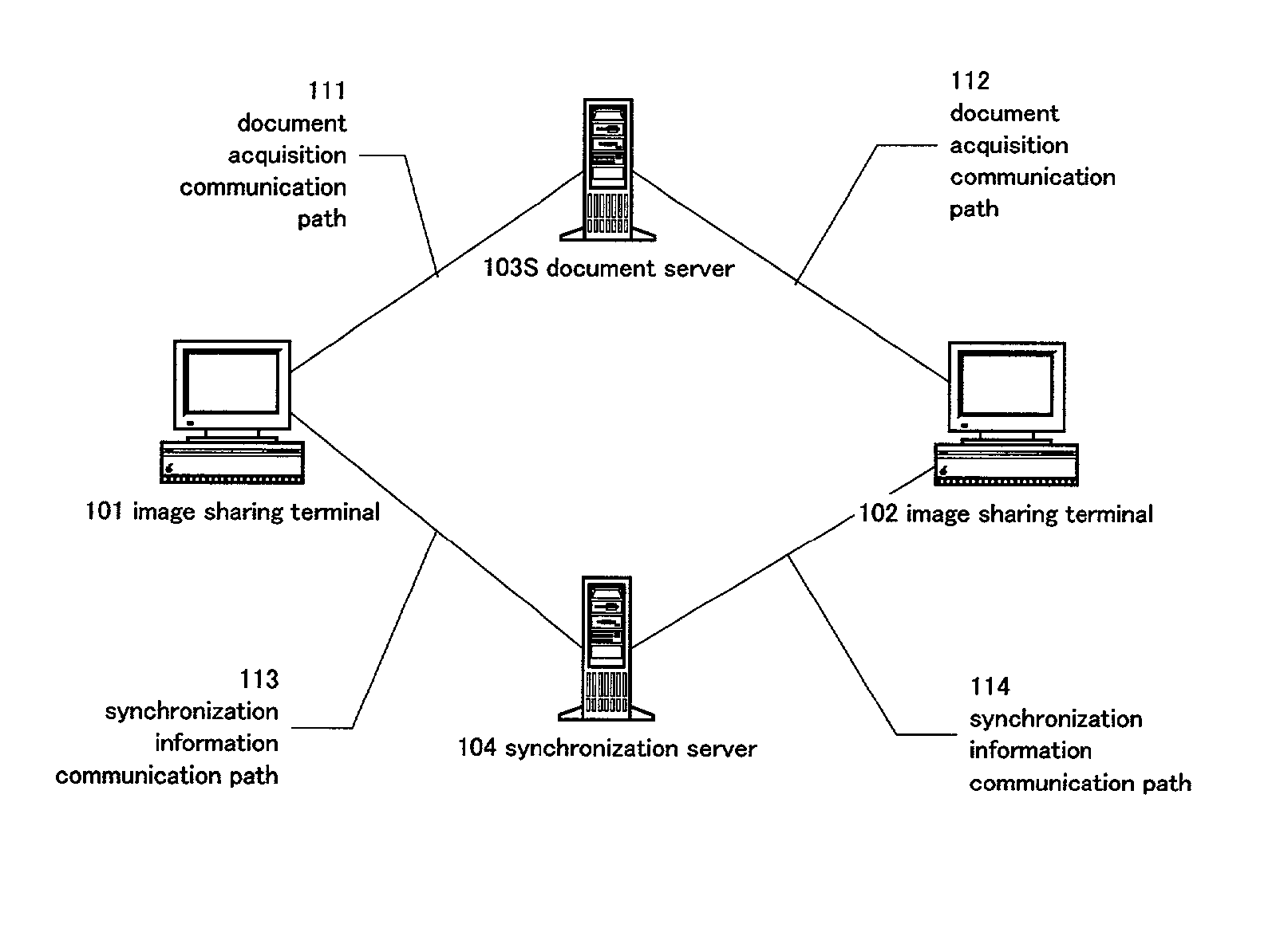
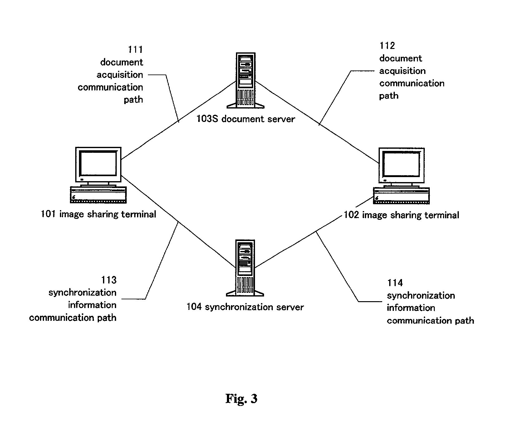
[0122] In embodiment 1 described up to this point, all image transitions and image changes are sent once as requests to the synchronization server (numeral 104 in FIG. 3) and are lined up in a queue held by the synchronization server. In addition, displaying of the same image at all of the terminals can be guaranteed because requests are made to execute requests at all terminals including the source of the transmission. The synchronization drift that occurred in the related image sharing systems therefore no longer occurs.
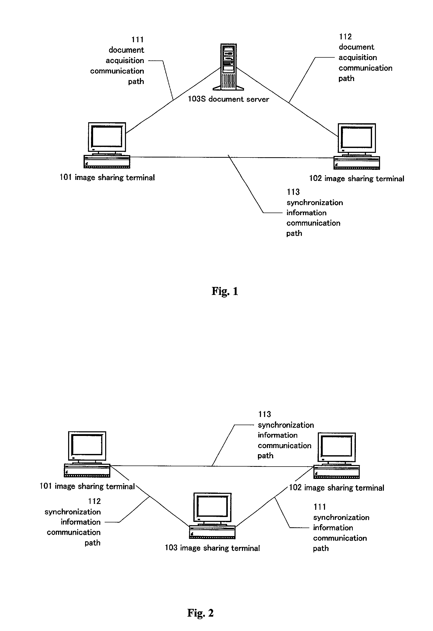
[0123] Sharing between scattered sites can also be processed effectively using this method. FIG. 8 shows a configuration when three of the image sharing terminals of FIG. 3 are provided (the document server 103S of FIG. 3 is omitted in FIG. 8).
[0124] Taking the number of terminals to be N, the number of communication paths is N. Special processing is not required even if the number of terminals is increased because each image sharing terminal only has to communicat...
second embodiment
[0125] The basic configuration of the second embodiment is the same as the configuration for the first embodiment in FIG. 3, but the configuration and operation of the synchronization server are superior. For ease of description, details of the request accumulator (corresponding to numeral 4R in FIG. 6) of the synchronization server in this embodiment are shown in FIG. 9.
[0126] FIG. 9 is a view showing various elements of the configuration within the request accumulator (corresponding to numeral 4R of FIG. 6) for the synchronization server (corresponding to numeral 104 of FIG. 3) of this embodiment. That indicated by numeral 101RA in FIG. 9 is the request accumulator. The request accumulator 101RA comprises a mapping table 1M and queues 2Q and 3Q. The left column of the mapping table 1M is an ID uniquely designating an element of the document, that connects the queues 2Q and 3Q. These queues are generated dynamically by the document structure and tasks are generated for the respecti...
first embodiment
[0147] Synchronization drifts do not occur in the method of the first embodiment, but there is a problem in that an excessive amount of time can be required to provide synchronism at the synchronization server when mutual inputting is carried out (the related art is rapid but synchronization drift occurs).
[0148] This is described in detail in the following with reference to FIG. 3.
[0149] For example, it is taken that a document configuration element A is edited at the image sharing terminal 101 and that a document configuration element B is edited at the image sharing terminal 102 at substantially the same time. Each image sharing terminal then detects edits, and sends change requests to the synchronization server. There are, however, occurrences where the request for element A issued from the image sharing terminal 101 of the two change requests arrives / is received first.
[0150] Assuming that there is nothing in the queues in the initial state of the synchronization server 104, in t...
PUM
 Abstract
Description
Claims
Application Information
 - R&D
- Intellectual Property
- Life Sciences
- Materials
- Tech Scout
- Unparalleled Data Quality
- Higher Quality Content
- 60% Fewer Hallucinations
Browse by: Latest US Patents, China's latest patents, Technical Efficacy Thesaurus, Application Domain, Technology Topic, Popular Technical Reports.
© 2025 PatSnap. All rights reserved.Legal|Privacy policy|Modern Slavery Act Transparency Statement|Sitemap|About US| Contact US: help@patsnap.com


