
Method and apparatus for resolving perspective distortion in a document image and for calculating line sums in images

Active Publication Date: 2003-02-06
XEROX CORP
View PDF9 Cites 80 Cited by
  • Summary
  • Abstract
  • Description
  • Claims
  • Application Information

AI Technical Summary

Problems solved by technology

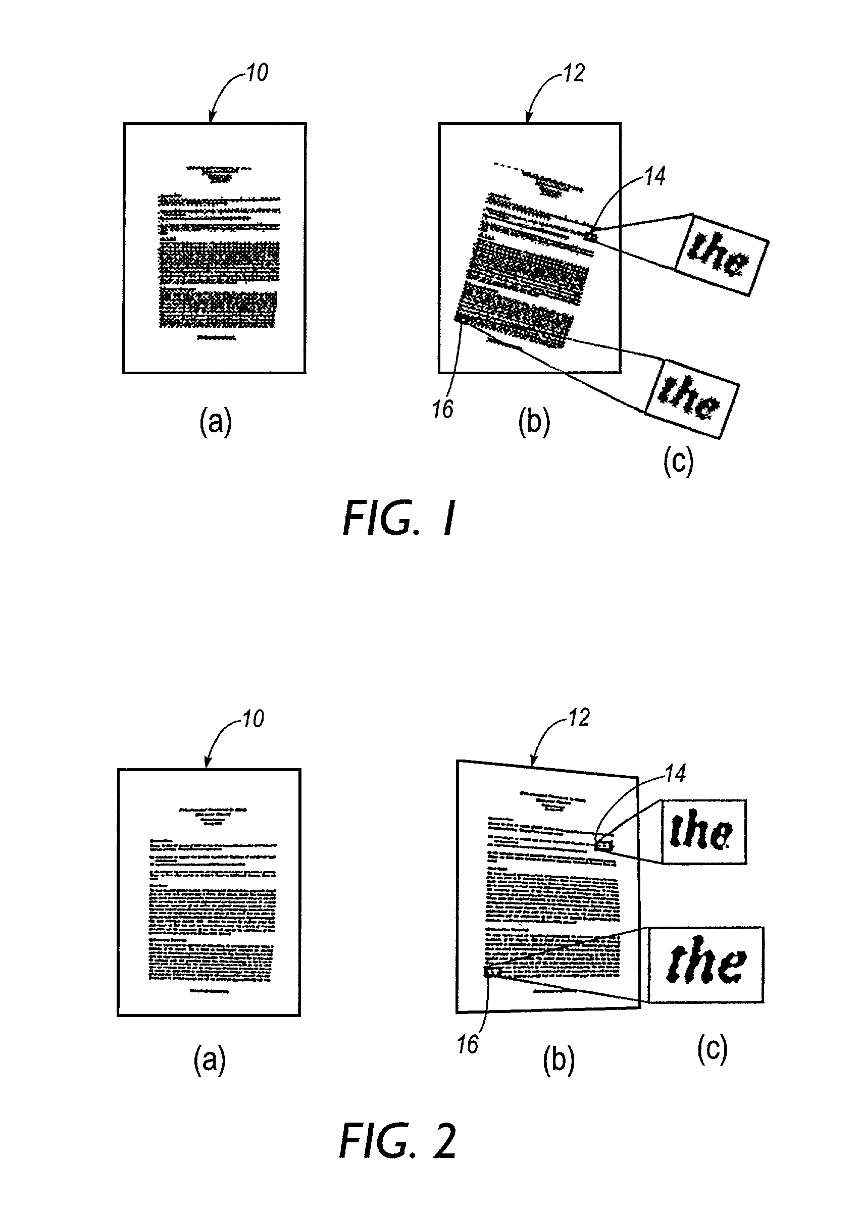
This can lead to degradation of the captured image, in particular degradation caused by perspective distortion in the captured image.
Such mis-positioning of the camera relative to the document plane is typical, as a user will often not be able to judge this accurately, or the user will avoid holding the camera in an awkward position.
An inexperienced user might not even be aware of the importance of camera position.
It is not possible to apply the usual skew-correction technique to detect and correct for perspective distortion because the skew-correction technique relies on there being a uniform angle of skew across the image.
The existence of perspective distortion in an image is highly undesirable.
Firstly, the human eye is highly sensitive to such distortion, and it makes the image unappealing and distracting to human readers.
Perspective distortion can also create serious problems for automatic image processing techniques which typically assume a "flat" document image without perspective, and may become complicated, slow and even unreliable in the presence of perspective distortions.
Automatic page layout analysis usually assumes the presence of horizontal and vertical white space, and so might not be effective if perspective distortion is present.
Also document image compression schemes may assume a non-perspective image, and might not be optimized for perspective distorted images.
The specific problem of correcting perspective distortion in document images is relatively new and unresolved, since document capture with cameras is itself a new and emerging field.
SPIE: Document Recognition and Retrieval VII, pages 267-277, 2000), such techniques do not perform reliably for general document images.

Method used


Image

  • Method and apparatus for resolving perspective distortion in a document image and for calculating line sums in images
  • Method and apparatus for resolving perspective distortion in a document image and for calculating line sums in images
  • Method and apparatus for resolving perspective distortion in a document image and for calculating line sums in images

Examples


example 1

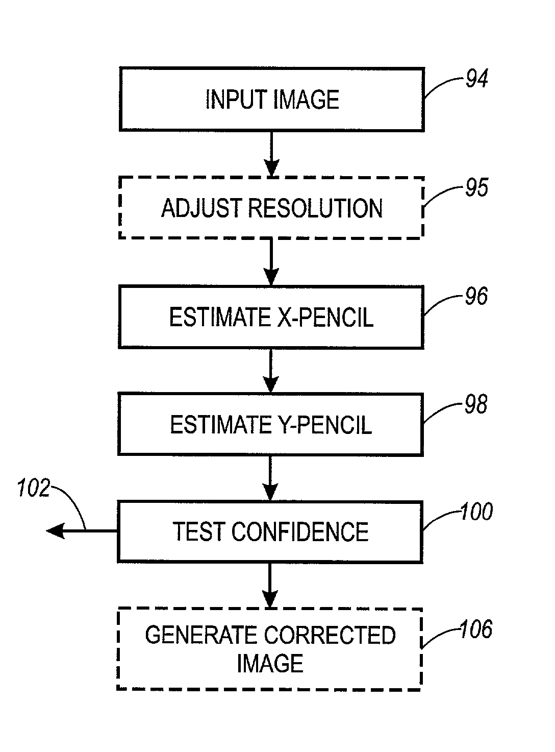
[0126] A first example of Y-pencil estimator will be described which is most similar to the X-pencil estimators described above. However, for reasons explained below, the second example of Y-pencil estimator is preferred in practice.

[0127] The Y-pencil estimator (in this first example) includes steps which are analogous to the steps 110, 116, 118, and 120 described with reference to the second example of the X-pencil estimator. Only the differences are described here.

[0128] In order to improve the SNR of the image for detecting Y-lines (such as justified column boundaries), the image is dilated (i.e., is made more black). Each black pixel is dilated into a 3.times.3 pixel structure (or larger structure, depending on the input image resolution and font sizes), followed by filling isolated holes. This has the effect of "filling in" the text characters to form continuous blocks representing the text columns. The borders of the columns are then extracted by taking a horizontal differenc...

example 2

[0133] To address the above problem, a second type of Y-pencil estimator has been developed. The following discussion assumes a binary (i.e., only black / white) image. The principles will be expanded in Example 3 to cover gray-scale images.

[0134] Referring to FIG. 13, the second technique is to select pixels in an image as being representative of a column border depending on the amount of white space adjacent to the pixel. Points which are adjacent to a relatively large white space are more likely to form part of a column boundary. A good choice for this white space should allow detection of as many aligned text edges as possible, but also as few spurious large white spaces as possible.

[0135] In this example, for computational convenience, a significant white space is detected by matching with a single shape. The shape should be quite tall in order that spaces in the middle of text lines can be eliminated from consideration by observing that a text line above or below does not have a...

example 3

[0160] In another alternate embodiment, the estimation is performed directly on a grayscale image. In X-pencil estimation, this is simply a matter of performing the initial line sums through the observed image as sums of gray values, other steps remaining as described for other embodiments. In Y-pencil estimation, a method based on grayscale morphology is employed for detecting points adjacent to large white triangles. This method actually reduces to that employed in the binary case (Example 2 above). Otherwise Y-pencil estimation proceeds as in other examples.

[0161] Referring to FIG. 15, the method firstly considers the detection of points with a white triangle of scale s to their left. For each point p (e.g., point 167), the maximum gray value in such a triangle (not including point p) is computed (e.g., triangle 168). This maximum is denoted by TL(p,s). The method then finds the minimum gray value of points in a square of side length s (e.g., square 169), which has the center of ...


PUM


Abstract

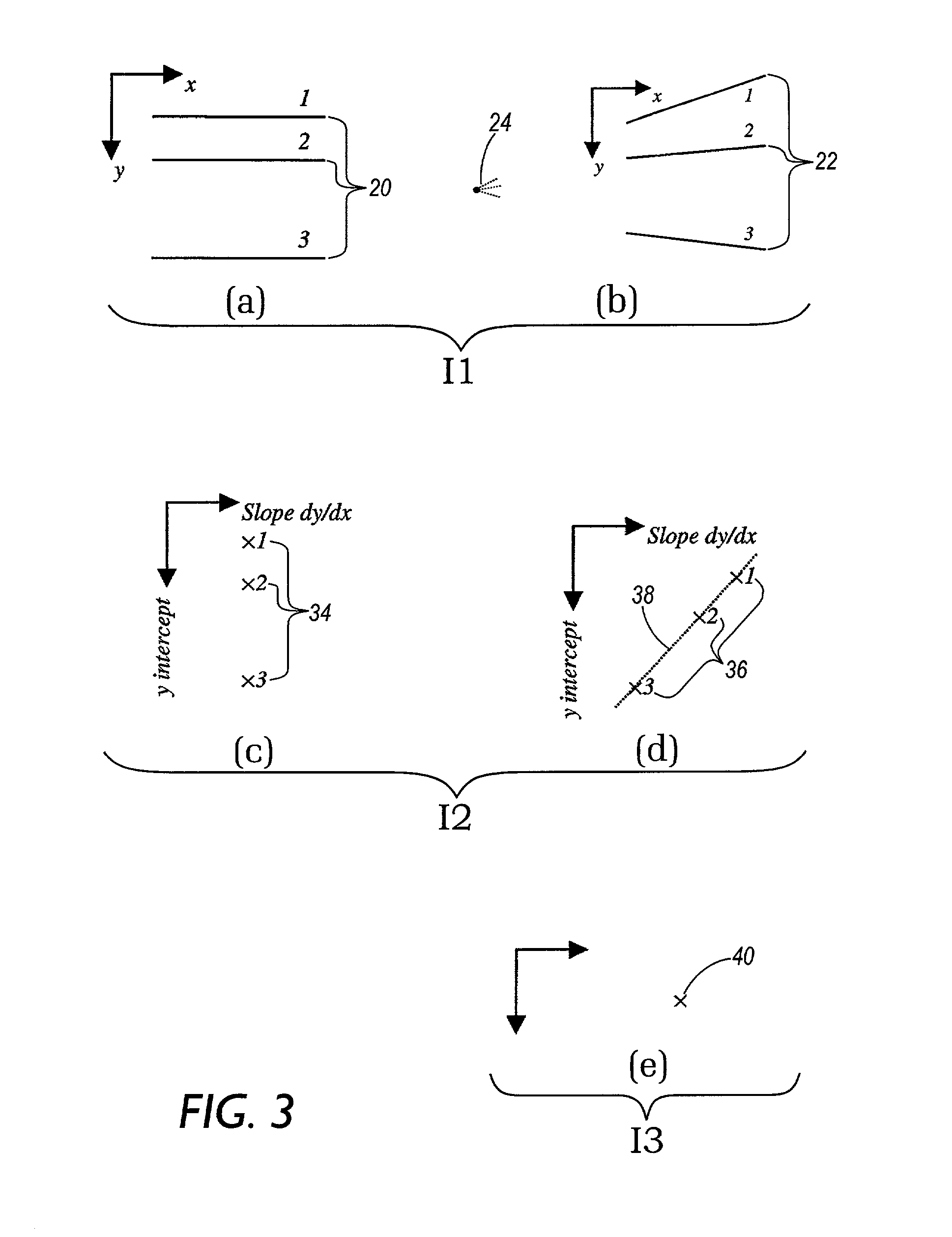
Perspective distortion is estimated in a digital document image by detecting perspective pencils in two directions, one being parallel to text lines, and the other being parallel to the boundaries of formatted text columns. The pencils are detected by analyzing directional statistical characteristics of the image. To detect a pencil, a first statistical line transform is applied to transform the image into line space, and a second statistical score transform is applied to transform the image into pencil space. A dominant peak in pencil space identifies the perspective pencil. In addition, a computationally efficient line summing technique is used for effecting sums of pixels along inclined target lines (or curves) through an image. The technique includes pre-generating partial sums, and summing along step segments of a target line using the partial sums.

Description

BACKGROUND TO THE INVENTION[0001] 1. Field of the Invention[0002] The present invention relates to processing digital pixel images.[0003] In one aspect, the invention relates to processing an image of a document and, in particular to resolving perspective distortion in the image. The invention is especially suitable for processing an image of a document captured using a digital camera, but the invention is not limited exclusively to this.[0004] In another aspect, the invention relates to performing a summing function along lines through the image. This technique may advantageously be used in the first aspect of the invention, but may find application in any image processing requiring a line sum along a line inclined relative to the image coordinate axes (for example, skew detection).[0005] 2. Description of Related Art[0006] There has been increasing interest in capturing a digital image of a document using a digital camera. A camera can be more convenient to use than a traditional ...

Claims


Application Information

Patent Timeline
IPC IPC(8): G06T5/00G06T7/60G06T3/00G06V30/10G06V30/166H04N1/387
CPCG06K9/325G06K9/3283G06K9/42G06T5/006G06V30/1478G06V20/62G06V30/10G06V30/166G06T5/80
Inventor DANCE, CHRISTOPHER R.
Owner XEROX CORP
Learn More