
Apparatus and method for digital processing of analog television signals

a technology of analog television and apparatus, applied in the field of synchronizing asynchronous signals, can solve problems such as significant problems such as audio synchronization and low error levels

Inactive Publication Date: 2003-01-09
PIXEL INSTR CORP
View PDF1 Cites 5 Cited by
  • Summary
  • Abstract
  • Description
  • Claims
  • Application Information

AI Technical Summary

Benefits of technology

[0015] An improved video synchronizer designed to allow synchronization of high quality video like signals while providing minimum distortion and maximum transparency.
[0017] A synchronizer which digitizes full sync tip to peak white video with low quantizing error and distortion.
[0025] A video synchronizer capable of selecting ones of the signals contained within the blanking areas, so that those signals may be preserved and passed with only the repetitive sync burst and blanking reconstructed and reinserted in the stored signals from the memory.
[0027] A synchronizer for video type signals in which reduction in size and power consumption is brought about by minimizing the electronic circuitry.

Problems solved by technology

The inventive features of the preferred analog embodiment however show the use of sophisticated digital signal processing techniques such as over-sampling and interpolation, such that these errors are kept to unexpected low levels.
With the widespread use of digital video processing, audio synchronization is becoming a significant problem.

Method used


Image

  • Apparatus and method for digital processing of analog television signals
  • Apparatus and method for digital processing of analog television signals
  • Apparatus and method for digital processing of analog television signals

Examples


Embodiment Construction

Single board case 1.75" H .times. 8.75" W .times. 17" D Six Board case 3.5" H .times. 19" W .times. 18.5" D 19" rack mount Twelve Board case 7" H .times. 19" W .times. 18.5" D 19" rack mount

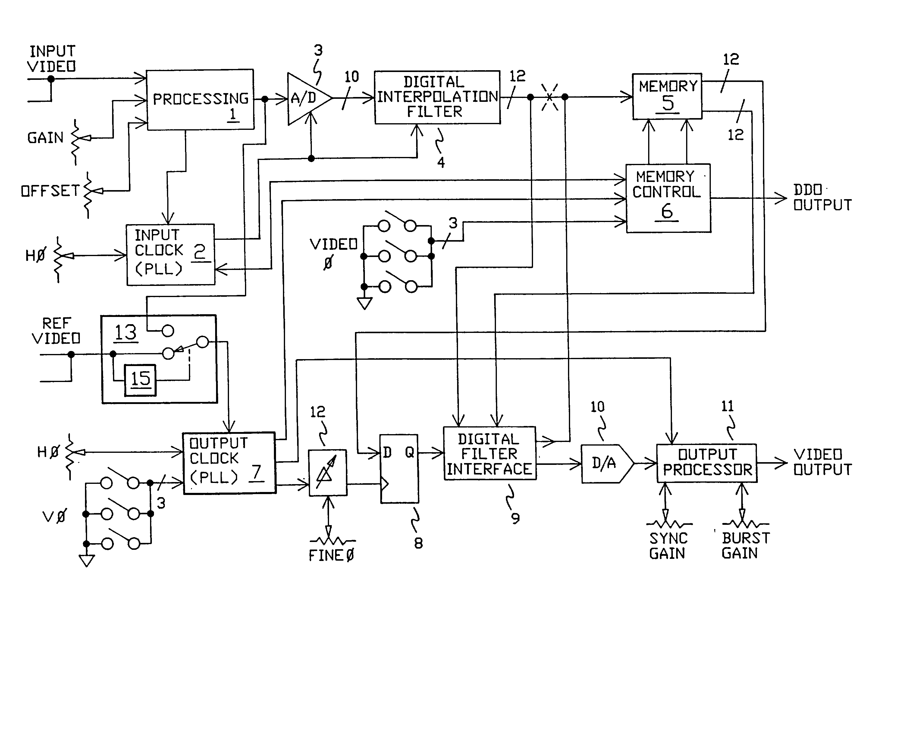
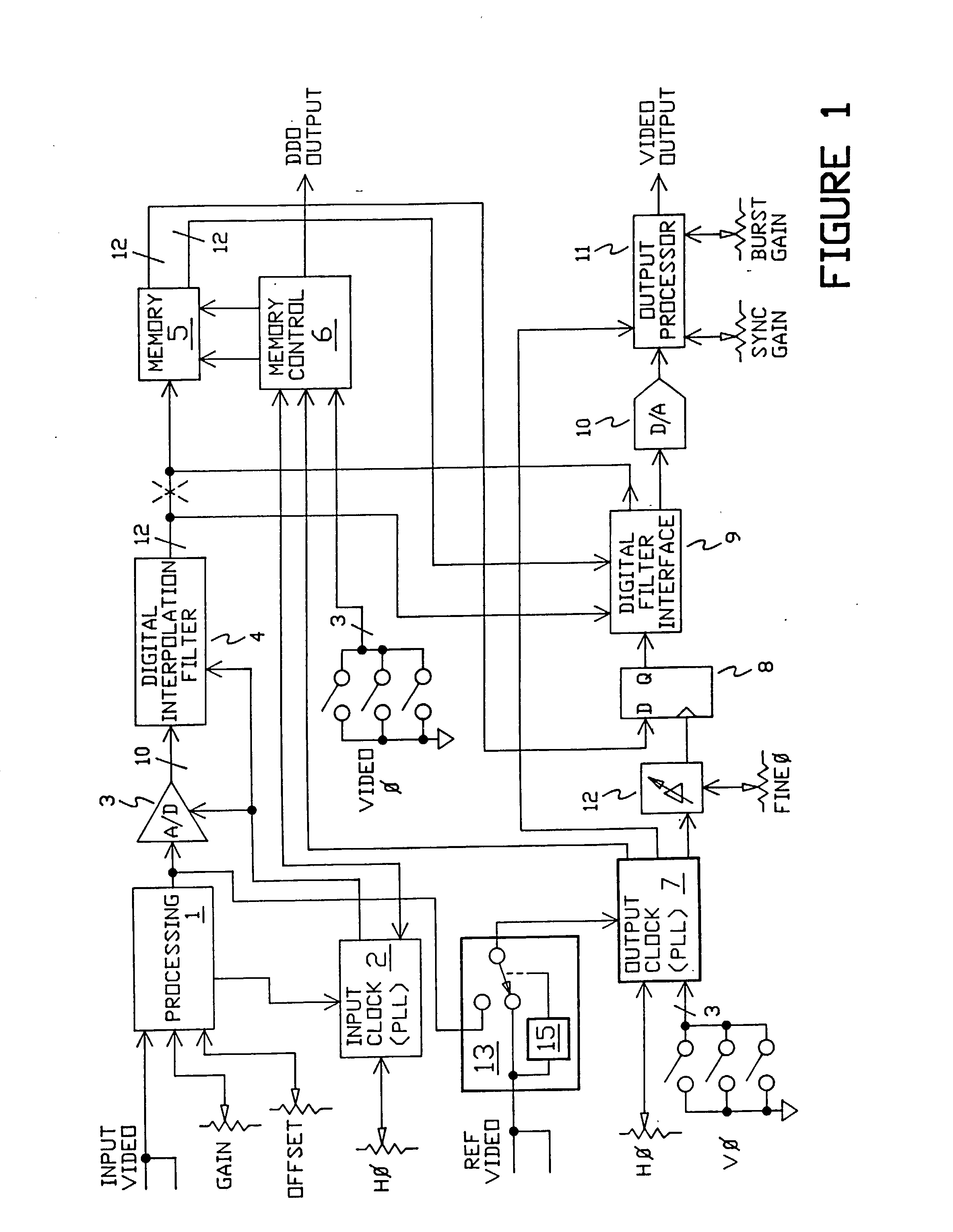
[0095] The diagram of FIG. 1 shows a video input terminal which is preferred to be of the high impedance looping type, which input is coupled to a processing section 1. The processing section operates to DC restore the video, remove common noise offset and noise, provide video gain and video offset to the video signal, which signal is coupled to the input of an Analog to Digital convertor section 3, and to a reference selecting section 13. In addition, the processing section 1 operates to recover synchronizing information from the input video signal, and couple this synchronizing information to the input clock section 2, which in the preferred embodiment contains a phase locked loop. The preferred embodiment operates to detect when the input signal is disrupted, with the memory responsive thereto...


PUM


Abstract

This invention is an apparatus and method for digital processing of television like signals and in particular the use of oversampling and interpolation to achieve improved resolution of the digital version of such signals as compared to a digital version obtained by the use of simple A / D conversion or processing at the desired sample rate. The preferred embodiment utilizes oversampling, interpolation and various filtering in recursive and nonrecursive form to provide output video signals wherein the artifacts and distortion of the video are kept to low levels.

Description

[0001] This application is a division of application Ser. No. 09 / 848,582 filed May 2, 2001 which in turn is a division of 09 / 627,618 filed Jul. 28, 2000, now U.S. Pat. No. 6,392,707 which in turn is a division of application Ser. No. 09 / 324,339 filed Jun. 2, 1999, now U.S. Pat. No. 6,141,057 issued Oct. 31, 2000 which in turn is a division of application Ser. No. 08 / 573,468 filed Dec. 15, 1995, now U.S. Pat. No. 5,946,049 issued Aug. 31, 1999, which in turn is a continuation in part of application Ser. No. 08 / 096,240 filed Jul. 26, 1993, now U.S. Pat. No. 5,550,594 issued Aug. 27, 1996. The above applications are incorporated herein by reference in their entirety for all purposes to the extent permitted by law as if fully set out herein. Unless explicitly defined herein, all words and phrases are intended to have their normal and ordinary meaning as used and understood by persons of ordinary skill in the art.[0002] 1. Field of the Invention[0003] The present invention relates to the...

Claims


Application Information

Patent Timeline
Patent Type & Authority Applications(United States)
IPC IPC(8): H04N5/073H04N9/475
CPCH04N5/0736H04N9/475
Inventor COOPER, J. CARLLOVELESS, HOWARDWALLEN, DAVIDVOJNOVIC, MIRKO
Owner PIXEL INSTR CORP
Learn More