
High-energy disposable medical stimulation electrode

a technology of electrodes and electrodes, which is applied in the field of medical electrodes, can solve the problems of not being able to conduct and distribute the high level of energy required, not being able to meet all defibrillation standards, and the stimulation electrodes disclosed are not capable of meeting the requirements of defibrillation standards, etc., to achieve efficient delivery of energy without burning the patient's skin, conduct energy sufficient for defibrillation, and improve current density distribution

Inactive Publication Date: 2003-01-02
KPR U S LLC
View PDF0 Cites 36 Cited by
  • Summary
  • Abstract
  • Description
  • Claims
  • Application Information

AI Technical Summary

Benefits of technology

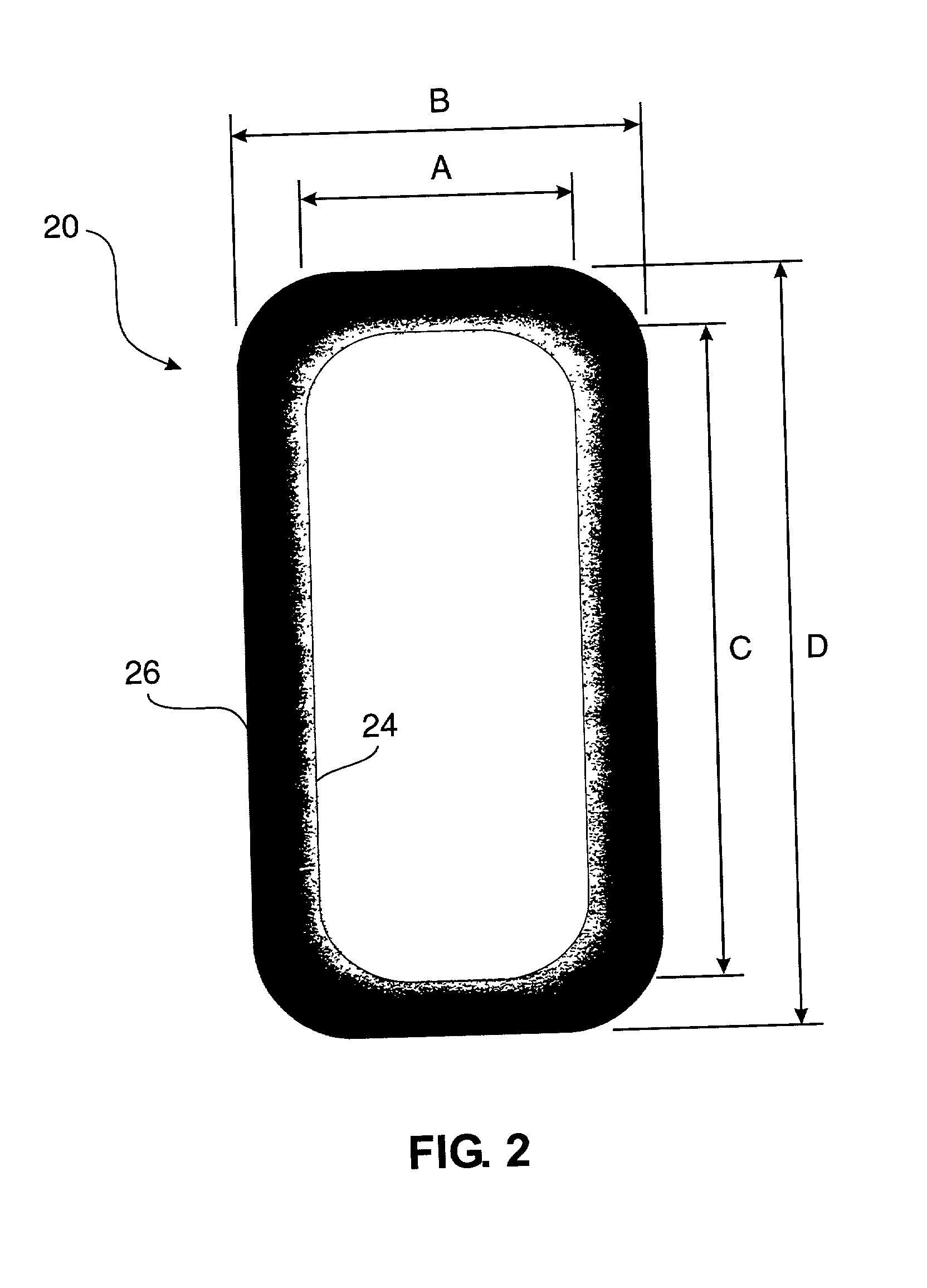
0021] To overcome the shortcomings of known defibrillation and pacing electrodes, a new disposable medical electrode intended for high-energy defibrillation and pacing with energy dispersion characteristics is provided. An object of the present invention is to provide a safe defibrillation electrode or set of electrodes which can compensate for impedance variances and can be economically manufactured, preferably in a continuous, automated process. A related object is to provide an improved electrode that features control of current density. Another object is to provide an electrode capable of conducting energy sufficient for defibrillation, and which has improved current density distribution between the electrode and the skin surface of the patient to efficiently deliver the energy without burning the patient's skin.

Problems solved by technology

In general, monitoring electrodes are not capable of conducting and distributing the high levels of energy required in transcutaneous stimulation and defibrillation electrodes.
Ferrari teaches that the sheet electrode as coated with the electrically conductive metal-metal chloride is not alone capable of transmitting and distributing the high levels of energy encountered in defibrillation over the entire surface of the electrode member.
Many of the stimulating electrodes that have been disclosed do not comply with all of the defibrillation standards.
The specification for defibrillation recovery characteristics, which describes certain time-related, electrical dissipation properties of the electrode following repeated electrical shocks of defibrillation currents, is especially difficult for many electrodes to meet.
The use of non-compliant electrodes would invite the possibility of an inordinate, life-threatening delay following defibrillation.
This restriction severely limits the usefulness of such electrodes in a critical care environment.
Many of the electrodes, especially those incorporating costly snap connectors or bilayered inks which require dual-step ink application, are undesirably expensive to manufacture.
Other known defibrillation electrodes have long defibrillation recovery times, impairing their ability to reliably function promptly after transmission of a defibrillation pulse through the electrode.
Still other electrodes fail to compensate for impedance variances.
Problems have been encountered with prior art defibrillation electrodes, particularly after application of repeated high-level defibrillation or cardiac pacing pulses, with irritation and burning of the patient's skin due to high current density around the perimeter of electrodes.
It also remains a problem to improve the x-ray transparency of defibrillation electrodes.

Method used


Image

  • High-energy disposable medical stimulation electrode
  • High-energy disposable medical stimulation electrode
  • High-energy disposable medical stimulation electrode

Examples


first embodiment

[0051] B. First Embodiment of the Present Invention

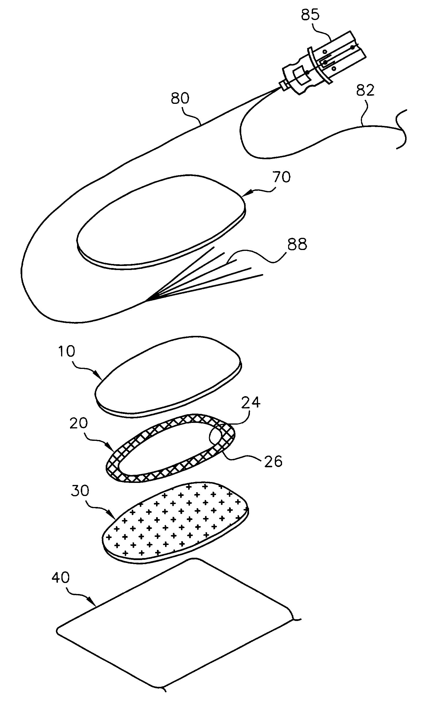
[0052] As illustrated in FIG. 1, the electrode construction according to the present invention has a release carrier sheet 40. The release carrier sheet 40 may be made, for example, of silicone-coated PET. Although not required, a rectangular shape is suitable for the release carrier sheet 40. If rectangular as illustrated, dimensions such as a length of about 140 mm and a width of about 82 mm are suitable.

[0053] An oval-shaped foam barrier 34, having a substantially constant width of about 5 mm and a thickness of about 1 mm, is disposed on, and adjacent the edges of, the release carrier sheet 40. The foam barrier 34 defines a central opening approximately 65 mm wide and 122 mm long, in which is disposed and retained the gel pad 30. An adhesive may be provided on the patient-facing side of the foam barrier 34 to releasably affix the electrode to the skin of the patient.

[0054] The cover sheet 70, a continuous foam backing sheet witho...

second embodiment

[0072] C. Second Embodiment of the Present Invention

[0073] Illustrated in FIG. 4 is a second, preferred embodiment of the electrode construction according to the present invention. The embodiment illustrated in FIG. 4 is similar in many respects to, although certain features are not shared with, the first embodiment illustrated in FIG. 1. With reference to FIG. 4, the electrode construction of the second embodiment has a release carrier sheet 40. Like the first embodiment, the release carrier sheet 40 may be made of silicone-coated PET and, although not required, have a rectangular shape. If rectangular as illustrated, dimensions such as a length of about 165 mm and a width of about 135 mm are suitable.

[0074] Unlike the first embodiment, the cover sheet 70 of the electrode construction of the second embodiment has a pear-shaped configuration. The cover sheet 70 is a continuous foam backing sheet without any openings and having a thickness of about 1 mm, a major axis of about 156 mm,...


PUM


Abstract

A disposable medical electrode for delivering high-energy defibrillation or pacing stimulation and having energy dispersion characteristics. A fanned wire contacts the top of an electrode member for delivering energy to and transmitting energy from the electrode. A hydrogel is disposed on the bottom of the electrode member and an electrically conductive metal / metal chloride ink coating underlies the hydrogel. The ink coating has (a) a center with a first amount of ink, (b) an inner edge defining the terminus of the center and a step at which the ink content of the ink coating drops from the first amount of ink to a lesser second amount of ink, (c) an outer edge defining the terminus of the ink, and (d) a predetermined gradient disposed between the inner edge at which the ink coating has the second amount of ink and the outer edge at which the ink is substantially absent.

Description

TECHNICAL FIELD[0001] The present invention relates generally to medical electrodes and, more particularly, to disposable medical electrodes intended for high-energy stimulation (i.e., defibrillation, pacing, and the like) with energy dispersion characteristics.BACKGROUND OF THE INVENTION[0002] Medical electrodes provide an electrical interface between a patient and monitoring equipment (e.g., an electrocardiograph device) or between a patient and stimulating equipment (e.g., interferential and iontophoresis devices). A specific type of stimulating electrode, used to provide an electrical interface between a patient and defibrillation equipment, must be capable of conducting the high-energy level required for defibrillation. The present invention focuses on high-energy defibrillation and pacing electrodes. The general characteristics of, and distinctions among, monitoring electrodes, general stimulating electrodes, and defibrillation electrodes are outlined below.[0003] A. Monitorin...

Claims


Application Information

Patent Timeline
Patent Type & Authority Applications(United States)
IPC IPC(8): A61N1/04
CPCA61N1/0428A61N1/046A61N1/0472A61N1/048A61N1/0492
Inventor GADSBY, PETER D.
Owner KPR U S LLC
Learn More