
Laminated edge filter structure and method of making

a technology filter element, applied in the field of laminated edge filter element structure and method of making, can solve the problems of filter failure test, membranes are relatively weak and fragile, and membranes do not seal well with potting materials

Inactive Publication Date: 2003-01-02
MILLIPORE CORP
View PDF19 Cites 20 Cited by
  • Summary
  • Abstract
  • Description
  • Claims
  • Application Information

AI Technical Summary

Benefits of technology

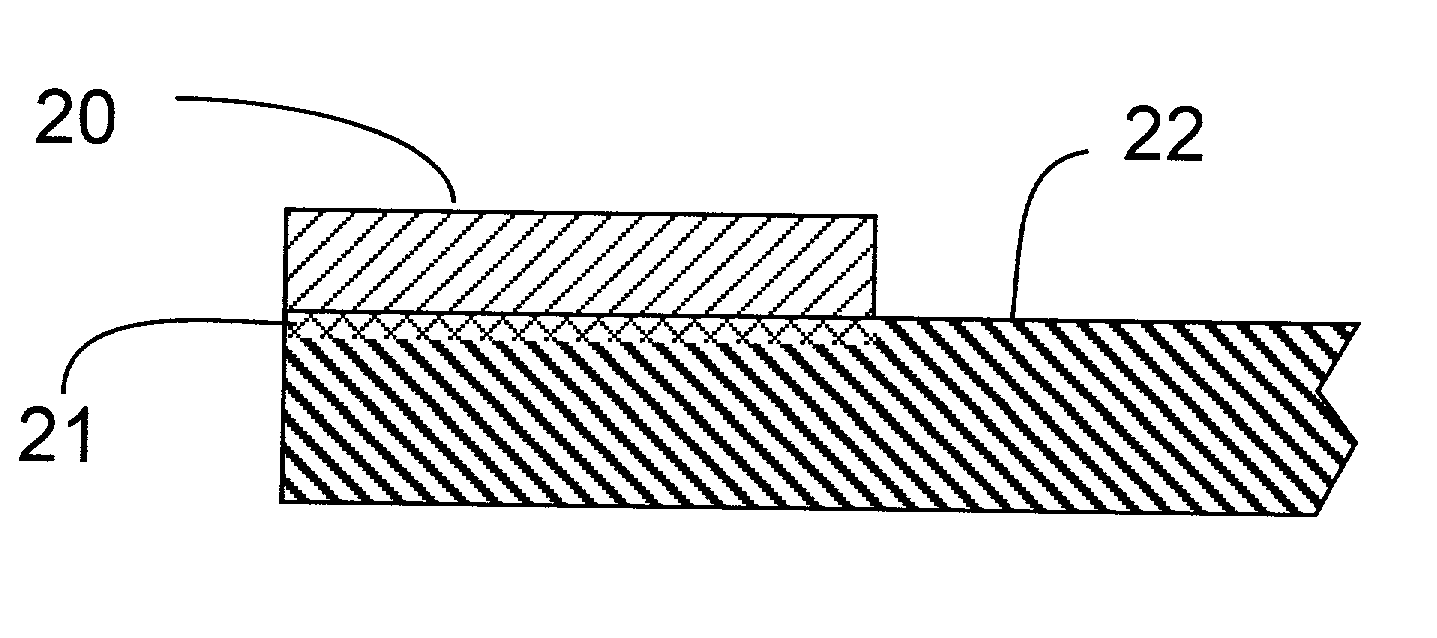
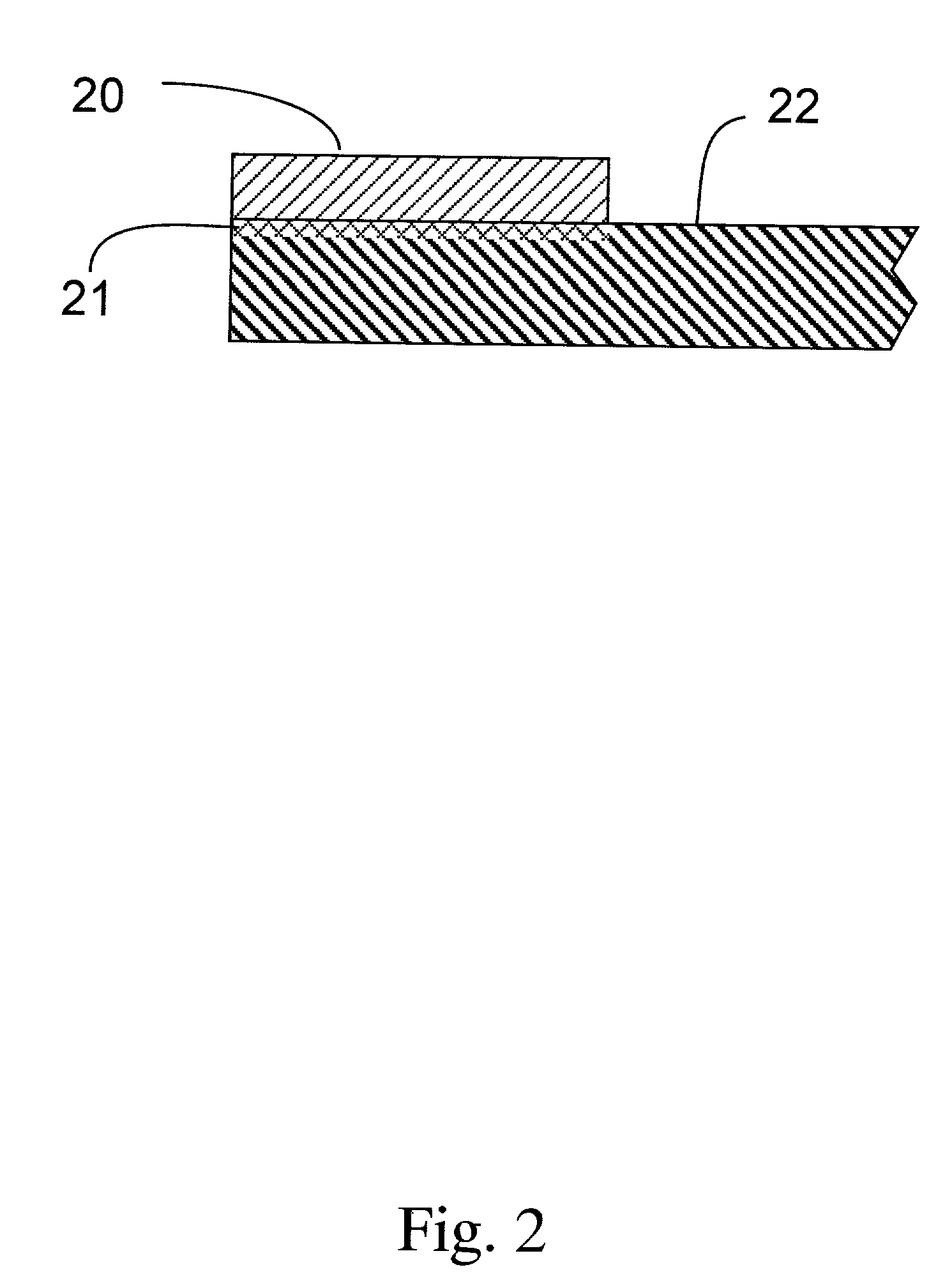
[0016] The present invention provides a product and process for making the product which allows for the formation of a sealing edge on a membrane that is integral and allows for a solid seal between the membrane and the potting material of the cartridge or capsule into which it is sealed. Additionally, it forms the edge without disrupting the hydrophilic coating in the edge area (if used). Moreover, it allows for the simultaneous formation of more than one membrane with the edge lamination at the same time and of the same of varying widths. Further, the invention provides for the use of multiple layers of membrane being sealed in the same edge material. Either by the use of one strip of material or by the use of multiple layers of strip material formed into a single edge piece.

Problems solved by technology

Such membranes are relatively weak and fragile especially when pleated.
Because of this dissimilarity between the polymers of the different components, the membranes do not seal well to the potting materials.
If the flow exceeds a set level, the filter fails the test.
Ordinarily the higher airflow is attributed to a physical defect in the filter such as a tear, pinhole, crack, bad seal or other such large opening.
However in many cases, the filter upon closer, destructive examination, such as SEM analysis, shows the device did not have a physical defect that caused the higher than allowed air flow.
This can cause several problems.
First, the loss of hydrophilicity reduces the effective amount of area that a given membrane has for filtration of philic liquids.
Lastly, and most importantly, this appears to interfere with the ability of the filter to pass the commonly used integrity test.
Thus, integral filters with no physical defects but some hydrophobic areas cannot be distinguished from philic filters that have physical defects such as defective seals or tears and are therefore rejected unnecessarily.

Method used


Image

  • Laminated edge filter structure and method of making
  • Laminated edge filter structure and method of making
  • Laminated edge filter structure and method of making

Examples


Embodiment Construction

[0051] Samples according to the Present Invention

[0052] Hydrophilic, PVDF membrane, known as Durapore.RTM. membrane available from Millipore Corporation of Bedford, Massachusetts, was sealed at its top and bottom edges on one side with an extrusion laminated strip of polypropylene and subsequently converted into pleated, 10 inch cartridges.

[0053] Control Samples

[0054] Hydrophilic, PVDF membrane, from the same manufacturing lot as the above samples was also heat laminated at the top and bottom edges of the membrane on one side, but with a preformed film of polypropylene. This structure was subsequently converted into pleated, 10-inch cartridges for comparison to the above samples.

[0055] Testing

[0056] Both sets of membrane were formed into 10 inch pleated cartridges formed of polypropylene nonwoven support, end caps and cages. All cartridges were formed in the same manner and under the same conditions.

[0057] All cartridges were subjected to a gas diffusion test in which cartridge inte...


PUM

PropertyMeasurementUnit
heightaaaaaaaaaa
heightaaaaaaaaaa
heightaaaaaaaaaa

Abstract

The present invention relates to a filter element having a non-porous extrusion laminated strip formed on at least one edge and at least one side of a membrane. The strip is used to provide a means for ensuring a good bond between the filter element and the material into which it is potted. The strip is formed by the use of one or more extrusion heads that apply molten or softened polymer to one or both of the surfaces of the filter in a width and height desired. The strip is then subjected to pressure such as through a nip to at least partially embed the polymer strip into the filter pores so as to create a strong mechanical bond between the strip and the filter element. Additionally, it allows for the simultaneous formation of more than one membrane with the edge lamination at the same time.

Description

[0001] The present invention relates to a laminated edge construction for a filter and a method of making it. More particularly, it relates to the use of an extrusion lamination process to form one or more sealed edges on one or more layers of filter in order to form an integrally sealed filter in a cartridge device,[0002] Filter media are available in a variety of materials, typically natural or synthetic polymers. The media is typically in the form of a sheet. Often this sheet is pleated to increase the amount of surface area in a given device, The side edges and ends are then sealed. The ends are typically potted into end caps that are then bonded to cartridge housings to complete the device. The ends are commonly sealed into the end caps by the use of liquid sealers such as epoxy or polyurethane, molten thermoplastics, and the like.[0003] The sheets are thin fibrous or cast porous membranes that have about 50 to 80% of their volume in the form of voids that form the pores of the...

Claims


Application Information

Patent Timeline
Patent Type & Authority Applications(United States)
IPC IPC(8): B01D63/00B01D61/08B01D61/18B01D63/06B01D63/14B01D65/00B01D65/10B01D69/00B01D69/12B01D71/16B01D71/20B01D71/26B01D71/32B01D71/34B01D71/36B01D71/50B01D71/56B01D71/68B29C70/76
CPCB01D63/061B01D63/067B01D65/003B01D65/102B01D65/104B01D69/00B01D69/12B29C70/763B29L2031/14B01D2313/44B01D2313/90B01D2319/06B01D2313/901B01D69/1213
Inventor PROULX, STEPHENDECOSTE, DAVIDLENTINE, FRANKCARROLL, MARKPEREIRA, BRIANPERIVOLOTIS, GEORGEBURNS, JOHN LEONARD JR.
Owner MILLIPORE CORP
Learn More