
Method for making large composite structures without use of an autoclave

a large-scale, composite material technology, applied in the direction of manufacturing tools, soldering devices, auxillary welding devices, etc., can solve the problems of differential stresses along the joint, the inability to welded composite materials including thermoset materials or reinforcements, and the complex bonding of composite materials to metallic materials or other composite materials

Inactive Publication Date: 2002-12-12
LOCKHEED MARTIN CORP
View PDF0 Cites 10 Cited by
  • Summary
  • Abstract
  • Description
  • Claims
  • Application Information

AI Technical Summary

Problems solved by technology

The fastening of composite materials to metallic materials or to other composite materials is complicated by the fact that composite materials including thermoset materials or reinforcements cannot, in general, be welded, because the matrix material, being organic, chars rather than melting, and the reinforcing material cannot be raised to a high enough temperature to fuse, without destroying the underlying matrix.
The use of fasteners such as bolts or screws creates differential stresses along the joint, and creates a sealing problem in those cases in which fluids, especially cryogenic fluids, are to be contained.
These problems are exacerbated when there is a difference between the temperature coefficients of expansion of the materials being fastened andor of the fastener.
Autoclaves cannot be used under all conditions, especially when large assemblages are to be cured.

Method used


Image

  • Method for making large composite structures without use of an autoclave
  • Method for making large composite structures without use of an autoclave
  • Method for making large composite structures without use of an autoclave

Examples


Embodiment Construction

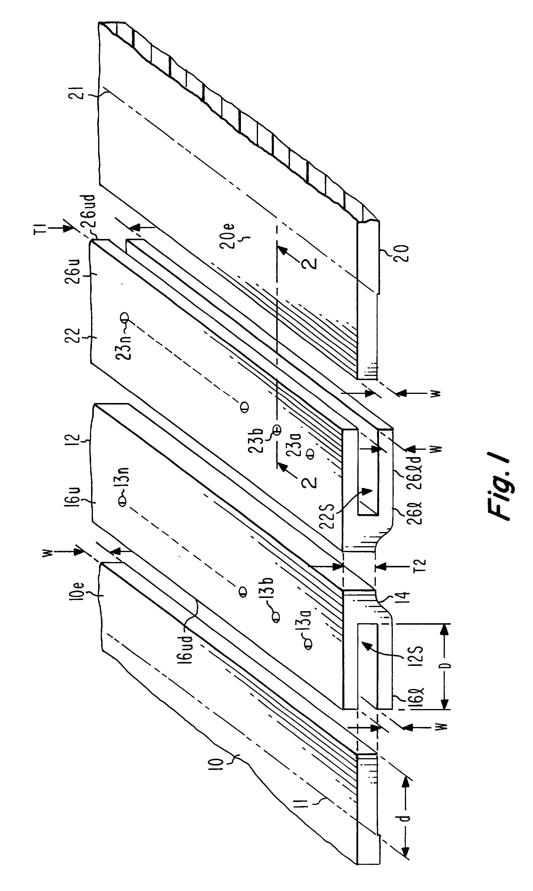
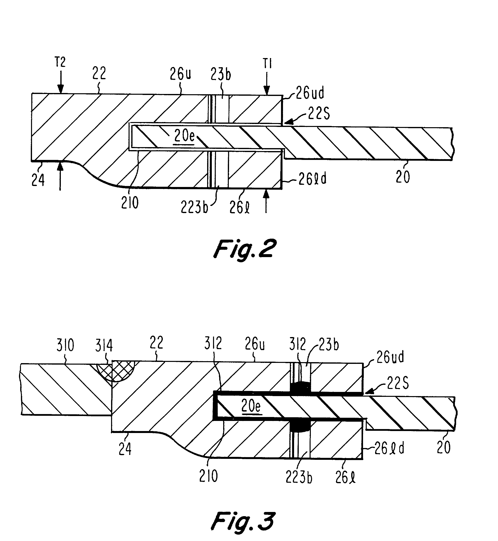
[0013] In FIG. 1, a first planar composite sheet 10 is associated with a first elongated metallic structure 12, and a second composite sheet 20 is associated with a second elongated metallic structure 22. Metallic structures 12 and 22 may be identical. As illustrated in FIG. 1 and in the cross-section of FIG. 2, metallic structure 12 is shaped, either by machining, casting or extrusion, as a bifurcated structure including a common heel or tang portion 14 and upper and lower tines or strip portions 16u and 16l, respectively. Those distal portions of the upper and lower tines which are most remote from the tang portion 14 are designated 16ud and 16ld, respectively. Upper and lower tine portions 16u and 16l run generally parallel, and define an elongated slot or notch 12S therebetween. The width W of the slot 12S is no less than the thickness w of the edge portion 10e of composite panel 10, and the depth D of slot 12 is at least slightly greater than the width d of edge portion 10e of ...


PUM

PropertyMeasurementUnit
thicknessaaaaaaaaaa
metallicaaaaaaaaaa
metallic structureaaaaaaaaaa

Abstract

A method for fabrication or production of composite structures, which has particular advantages when fabricating large structures, includes the steps of procuring a composite panel, such as carbon-fiber-reinforced resin. The edge of the composite panel is adhesively fixed in the slot of a bifurcated metallic piece. After the composite panel is adhesively fixed to the metallic piece, the metallic piece is stir-friction welded to another metal piece. The stir-friction welding occurs at a lower temperature than fusion welding, and so the adhesive bond between the metallic element and the composite panel is less affected. When two composite panels are each adhesively fastened to a metallic element, the two metallic elements can, in turn, be stir-friction welded. Thus, large panels can be fabricated.

Description

[0001] This invention relates to the edge fastening of panels or sheets of material, and more particularly to such fastening including both adhesive joints and stir-friction welded joints.[0002] The fastening of composite materials to metallic materials or to other composite materials is complicated by the fact that composite materials including thermoset materials or reinforcements cannot, in general, be welded, because the matrix material, being organic, chars rather than melting, and the reinforcing material cannot be raised to a high enough temperature to fuse, without destroying the underlying matrix. Composite materials are very advantageous for many purposes, as they combine high strength with low weight. Practical use of composite materials often requires that they be fastened to other composite structures or to metallic materials.[0003] In general, composite structures can be fastened to other structures by either the use of fasteners or by co-curing. The use of fasteners s...

Claims


Application Information

Patent Timeline
Patent Type & Authority Applications(United States)
IPC IPC(8): B23K33/00B29C65/00B29C65/54B29C65/64F16B11/00
CPCB23K33/00B29C65/64B29C66/12441B29C66/721F16B11/004B29C65/4835B29C65/542B29C66/12445B29C66/12469B29C66/742B29C66/474F16B11/006B29C66/8322
Inventor IWANCZYK, TIMOTHY DENNISARBEGAST, WILLIAM JOHN
Owner LOCKHEED MARTIN CORP
Learn More