Internal combustion engine control system

a control system and combustion engine technology, applied in the direction of machines/engines, non-mechanical valves, output power, etc., can solve the problems of increased pumping loss, reduced combustion efficiency, and increased loss, so as to reduce fuel consumption, reduce pumping loss, and achieve satisfactory combustion

Inactive Publication Date: 2002-10-17
HITACHI LTD
View PDF0 Cites 18 Cited by
  • Summary
  • Abstract
  • Description
  • Claims
  • Application Information

AI Technical Summary

Benefits of technology

0007] It is an objective of the present invention to provide an internal combustion engine control system for controlling an internal combustion engine, capable of greatly reducing

Problems solved by technology

Accordingly, it is difficult to achieve optimum valve timing control in a wide range of operating condition.
In an engine which is provided with a throttle valve disposed before an intake system to regulate the quantity of intake air and regulates the quantity of fuel to be injected according to the quantity of intake air, the pressure in the intake pipe is lower than the atmospheric pressure in an operating range in which the load on the engine is relatively low, energy necessary for lowering the piston, i.e., energy necessary to achieve a suction stroke (pumping loss) increases, the ratio of pumping loss to engine output increases and fuel consumption increases.
The prior art technique, however, keeps the lift of the intake valve and the opening angle fixed and does not control the

Method used


Image

  • Internal combustion engine control system
  • Internal combustion engine control system
  • Internal combustion engine control system

Examples


first embodiment

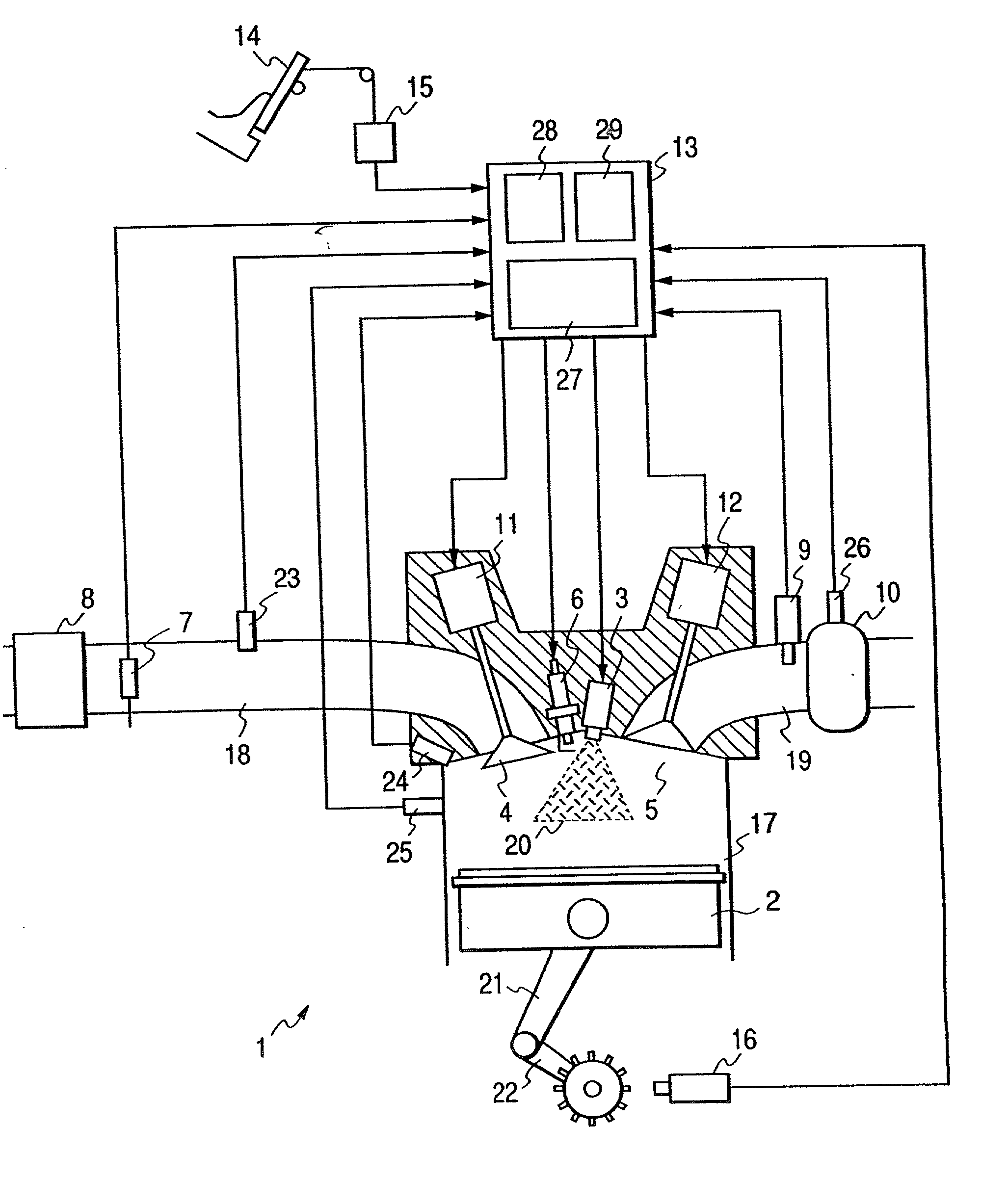
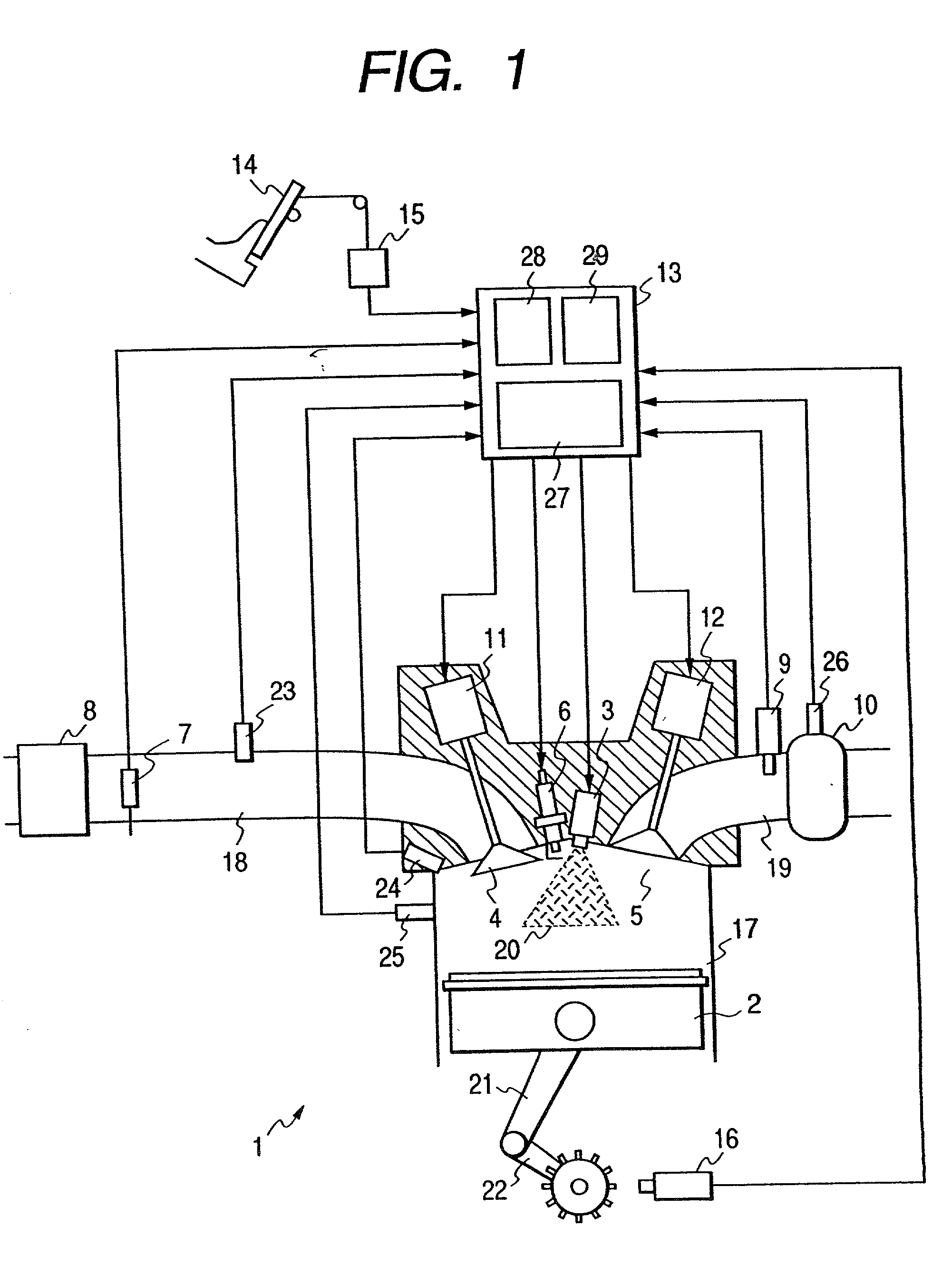
[0031] FIG. 1 is a view showing the configuration of the present invention and illustrating one of the cylinders of an engine in a sectional view. Referring to FIG. 1, an engine 1 is provided with a piston 2, a fuel injector 3, a intake valve 4, an exhaust valve 5, an ignition plug 6, a combustion chamber pressure sensor 24 for sensing pressure in a combustion chamber, and a knocking sensor 25. A intake pipe 18 is provided with an air flow sensor 7, an air cleaner 8 and a intake pipe pressure sensor 23 for sensing pressure in the intake pipe 18. An exhaust pipe 19 is provided with an air / fuel ratio sensor 9, a catalytic unit 10, and a catalyst temperature sensor 26 for sensing catalyst temperature, i.e., the temperature of the catalytic unit 10. Signals provided by the air flow sensor 7, the intake pipe pressure sensor 23, the combustion chamber pressure sensor 24, the knocking sensor 25, the air / fuel ratio sensor 9, the catalyst temperature sensor 26 and a crank angle sensor 16 are...

second embodiment

[0060] FIGS. 12 and 13 show the present invention. FIG. 12 is a graph showing the variations of valve lift, fuel injection quantity and air / fuel ratio with the stepping-on measurement of an accelerator pedal. A stepping-on measurement of the accelerator pedal represents an engine output demanded by the driver. It is considered that a high engine output is demanded when stepping-on measurement of the accelerator pedal is large, and it is considered that not a very high engine output is demanded when stepping-on measurement of the accelerator pedal is small. An engine like that of the present invention not provided with any throttle valve in the intake system needs to control intake air quantity to be sucked into the combustion chamber of the engine by the intake valve. Since the quantity of air flowing through the intake valve is roughly proportional to the area of an opening formed by lifting the intake valve, air quantity can be estimated from the lift of the intake valve. This met...

third embodiment

[0062] FIG. 14 is a graph of assistance in explaining the present invention. Usually, engine output is increased by increasing intake air quantity to provide driving power for driving an engine accessory, such as an air conditioning system while an engine is operating under a very light load, i.e., while the engine is idling. In a conventional engine provided with a throttle valve, intake air quantity is regulated by opening and closing a bypass passage bypassing the throttle valve by a valve disposed in the bypass passage for the fine adjustment of air quantity without opening the throttle valve, which, however, increases the number of parts and increases the costs. In the engine 1 illustrated in FIG. 1, the variable valve timing mechanism of the present invention keeps the open period and the valve lift of the intake valve constant and regulates intake valve opening timing and suction valve closing timing minutely to regulate the engine speed and the driving force of the engine. W...


PUM


Abstract

In an internal combustion engine control system for controlling an internal combustion engine, comprising a fuel injection control means for controlling fuel injection quantity to be injected by a fuel supply system for supplying fuel to the internal combustion engine, and fuel injection timing, and a variable valve control means for continuously or gradually varying at least opening timing, closing timing or lift of a intake valve or an exhaust valve for sealing up a combustion chamber of the internal combustion engine, the fuel injection control means controls at least fuel injection quantity or fuel injection timing on the basis of a value of a controlled variable provided by the variable valve control means. Since air quantity can be regulated by a variable valve timing mechanism, pumping loss and fuel consumption can be reduced. Fuel injected into the combustion chamber can be atomized by opening the intake valve so that a shock wave is generated in the combustion chamber and, consequently, stable combustion can be achieved without deteriorating the quality of the exhaust gas.

Description

[0001] The present invention relates to an internal combustion engine control system for controlling an internal combustion engine and, more particularly, to an internal combustion engine control system for controlling intake air and fuel in an internal combustion engine.[0002] Generally, the timing of operations of the intake valve and the exhaust valve of engines including direct fuel injection engines is dependent only on the cam profiles of cams driven for rotation in synchronism with the rotation of the crankshaft of the engine. Accordingly, it is difficult to achieve optimum valve timing control in a wide range of operating condition. It is desirable to vary valve timing according to the operating condition to improve the output performance of the engine and the like. It is necessary to vary valve timing so that valve overlap period, i.e., a period in which both the intake and the exhaust valve are open, decreases to prevent the blowby of new charge while the engine is operati...

Claims


Application Information

Patent Timeline
IPC IPC(8): F01L1/34F01L9/10F01L13/00
CPCF01L1/34F01L9/02Y02T10/18F02D13/0226F02D13/0253F01L13/0015Y02T10/12F01L9/10
Inventor SHIRAISHI, TAKUYAOHSUGA, MINORUFUJIEDA, MAMORU
Owner HITACHI LTD
Why Eureka
Try Eureka