
Garment dispensing and receiving apparatus having a removable cartridge body and a flexible dispensing door

Inactive Publication Date: 2002-09-19
INNOVATIVE PROD ACHIEVEMENTS
View PDF0 Cites 61 Cited by
  • Summary
  • Abstract
  • Description
  • Claims
  • Application Information

AI Technical Summary

Benefits of technology

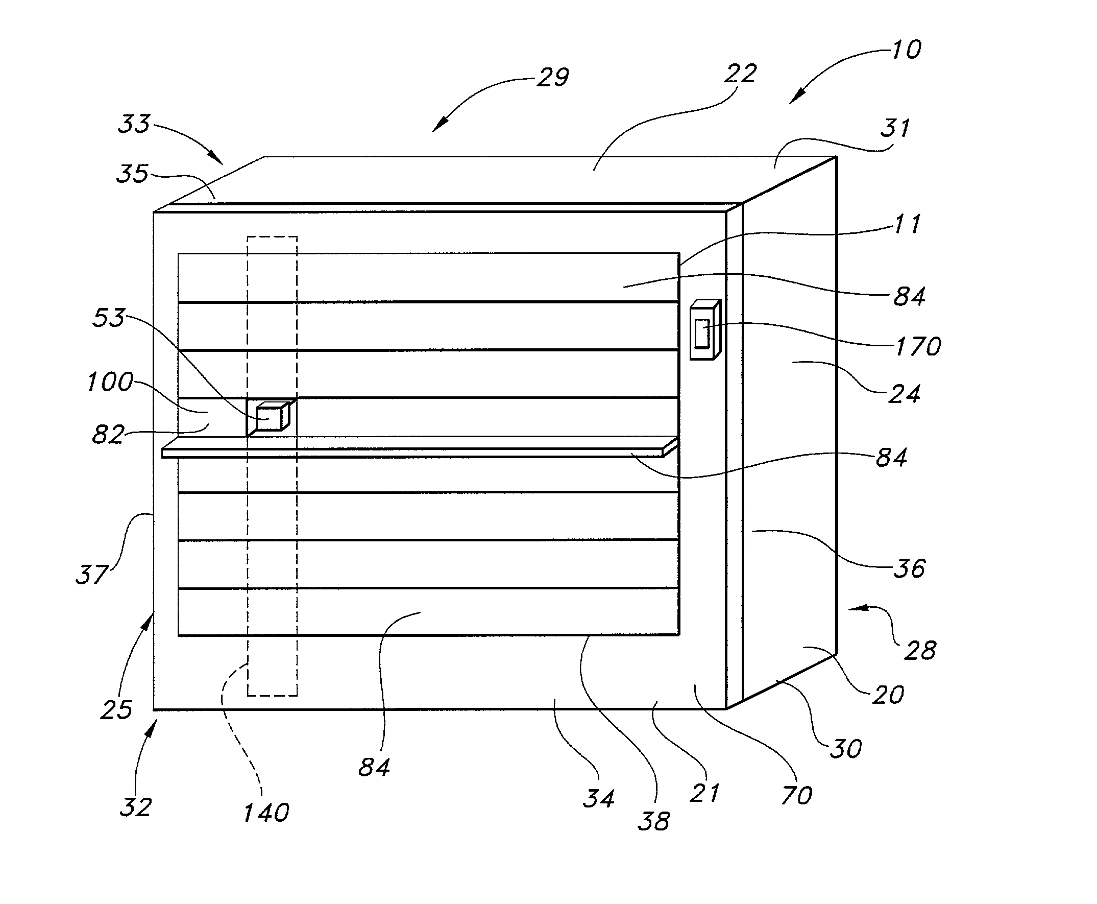
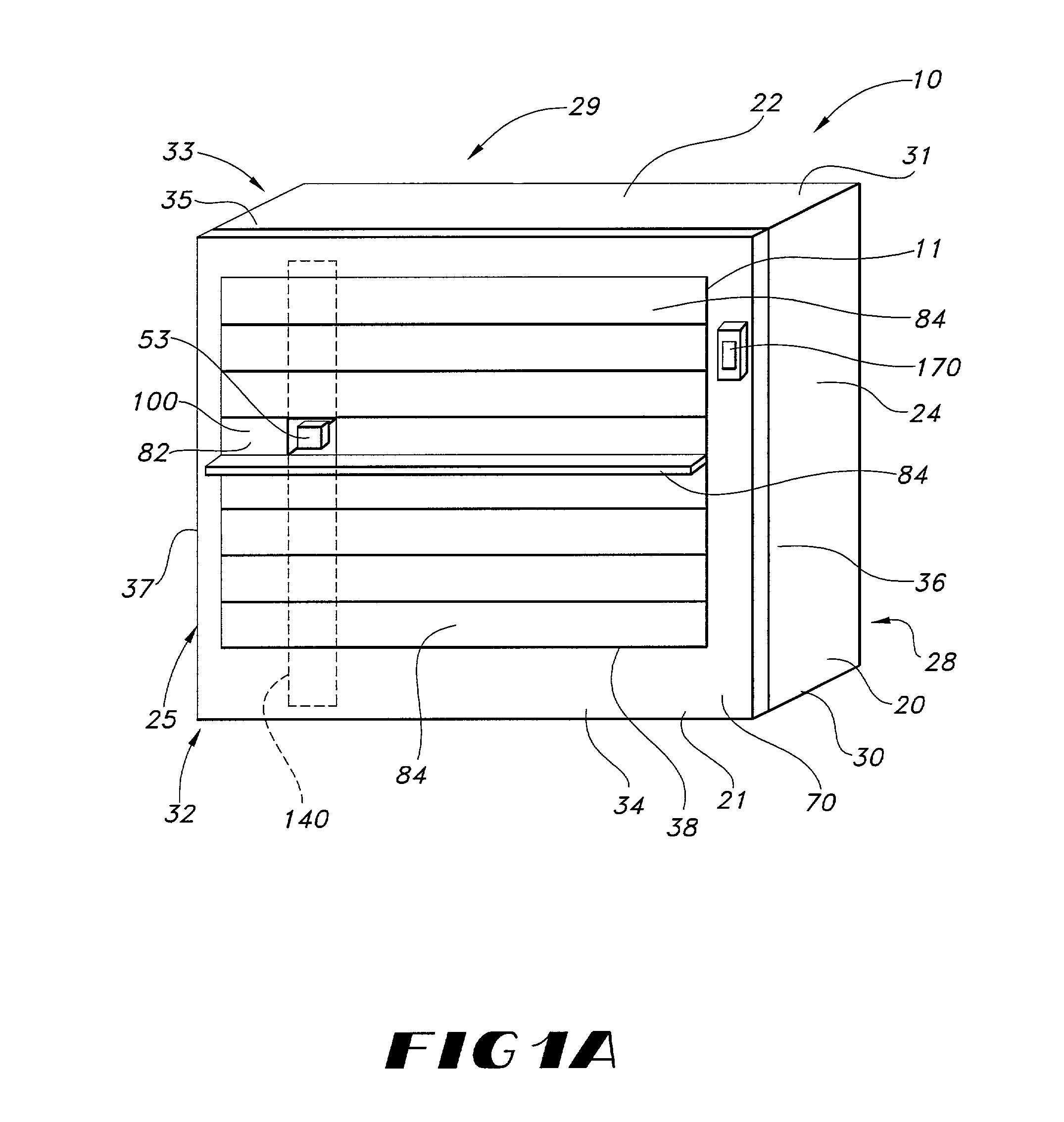
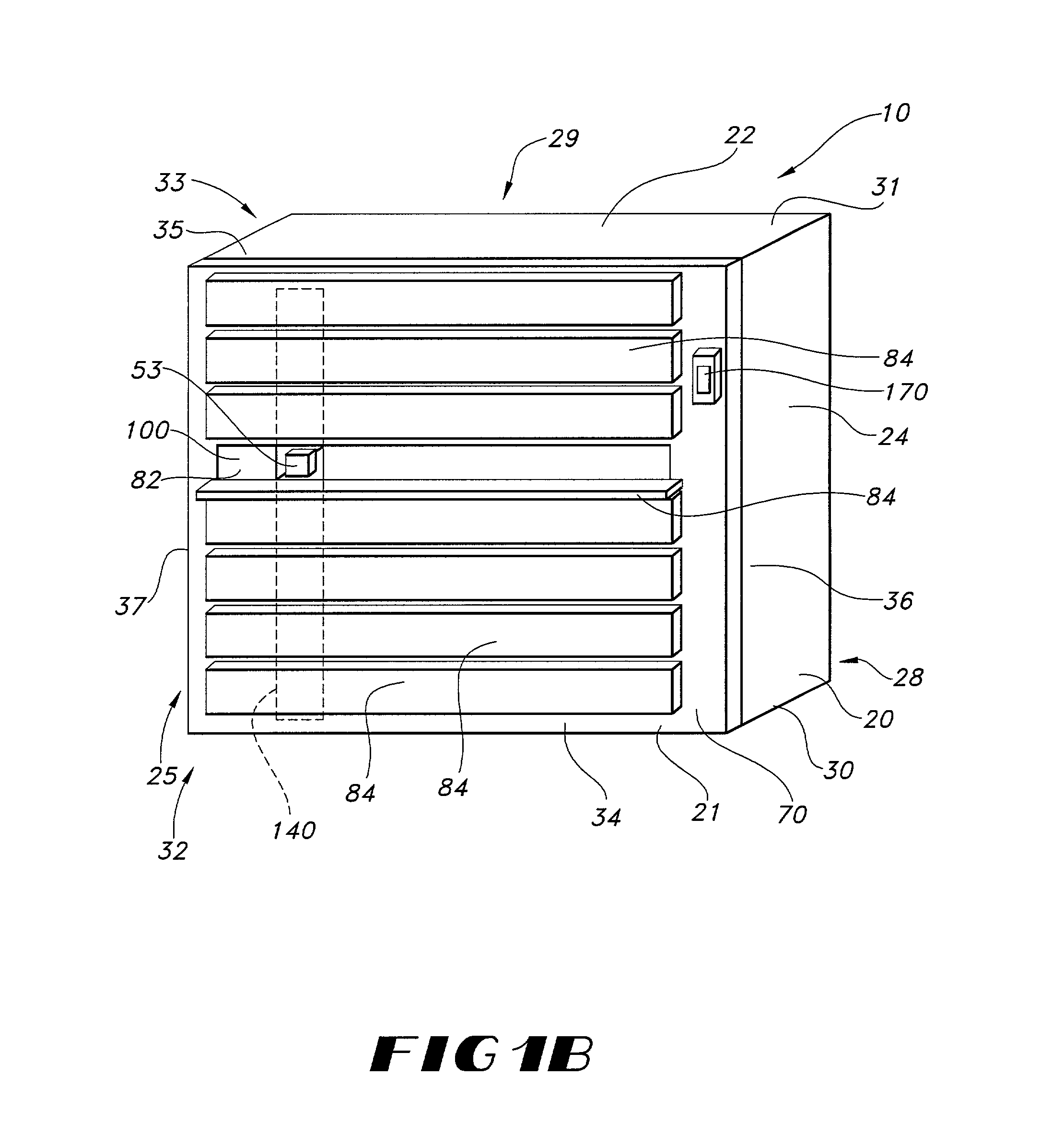
[0011] The present invention seeks to provide a compact dispensing apparatus and method that contains relatively few moving parts, that is inexpensive to manufacture and repair, and that may be loaded at a convenient location. The present invention accomplishes this by providing an array of receptacles for receiving goods to be vended, and a receptacle door that is disposed adjacent to the array of receptacles and that comprises at least one sheet of flexible material. The receptacle door is mounted for movement relative to the array of receptacles and defines an access region that selectively allows access to an interior of one or more of the receptacles while simultaneously blocking access to an interior portion of the other receptacles in the array.
[0023] After the dispenser has been properly loaded, a user may request a particular type of item by entering a request via the control mechanism. The control mechanism then reviews the dispenser's pre-programmed memory and identifies a target receptacle containing an item that meets the criteria entered by the user. The control mechanism then drives the drive mechanism to move the receptacle door laterally until the vertical opening in the receptacle door is aligned with a target column of cartridges that includes the target receptacle. Once the opening has been properly aligned, the receptacle door prevents access to the interior of all of the receptacles that are not within the target column of receptacles.
[0027] In another embodiment of the invention, the receptacle door is provided with a plurality of vertical plastic support slats that are sewn or riveted into the receptacle door and that are spaced apart along the length of the receptacle door. These support slats extend between slots that are adjacent the upper and lower edges of the main door. The slats serve to keep the receptacle door from drooping under its own weight or from being pushed down or up by someone trying to gain access to receptacles that are normally covered by the receptacle's door.
[0030] In yet another embodiment of the invention, the cartridge includes a series of horizontal shelves that are configured to receive packages of articles to be dispensed from the dispenser. These packages are divided by internal dividers into individual receptacles, which are loaded with articles prior to shipping. This allows the operator to load a whole row of the cartridge by simply removing the top of the package to expose the individual articles stored within their individual receptacles, and then placing the open package on the appropriate horizontal shelf. This significantly reduces the time required to load the cartridge.

Problems solved by technology

Although soiled scrubs are collected for laundering and subsequent reuse, the scrubs must be periodically replaced due to the wear and tear encountered in normal use.
These and other improper uses of scrubs contribute to an unacceptable reduction in most hospitals' inventories of scrubs.
Although this approach can help to solve the problems mentioned above, the approach is expensive to implement because it requires paying employees to distribute the garments twenty-four hours a day, seven days a week.
However, standard vending machines are not ideal for dispensing scrubs.
These vending machines, which store items on deep shelves and which dispense items by pushing the items individually over the edge of the shelves so that the items fall into a receiving bin, are too bulky to be placed in hallways or other locations where scrubs dispensers are needed.
Like the standard vending machines discussed above, these machines also have a size disadvantage because at least two dimensions of the machine (for example, depth and width) must be the same to accommodate the round pinwheel.
Despite the success of the vending machine taught in our U.S. Pat. No. 5,638,985, it is mechanically more complex than the proposed machine.
Additionally, while the dispenser is being loaded, it is "out of service".

Method used


Image

  • Garment dispensing and receiving apparatus having a removable cartridge body and a flexible dispensing door
  • Garment dispensing and receiving apparatus having a removable cartridge body and a flexible dispensing door
  • Garment dispensing and receiving apparatus having a removable cartridge body and a flexible dispensing door

Examples


Embodiment Construction

[0049] The present invention now will be described more fully hereinafter with reference to the accompanying drawings, in which preferred embodiments of the invention are shown. This invention may, however, be embodied in many different forms and should not be construed as limited to the embodiments set forth herein. Rather, these embodiments are provided so that this disclosure will be thorough and complete, and will fully convey the scope of the invention to those skilled in the art. Like numbers refer to like elements throughout.

[0050] Many modifications and other embodiments of the invention will come to mind to one skilled in the art to which this invention pertains having the benefit of the teachings presented in the foregoing descriptions and the associated drawings. Therefore, it is to be understood that the invention is not to be limited to the specific embodiments disclosed and that modifications and other embodiments are intended to be included within the scope of the app...


PUM


Abstract

A dispenser for dispensing articles such as scrub garments. The dispenser includes a housing that defines an interior portion, a foldable, wheeled distribution cartridge defining an orthogonal array of receptacles for receiving items to be distributed from the dispenser; and a main door for controlling access to the interior of each of the various receptacles. The main door defines a plurality of rectangular horizontal openings, each of which aligns with a horizontal row of receptacles within the distribution cartridge. Access to each of these horizontal openings is controlled by a lockable main door. A flexible receptacle door having a vertical opening is mounted on mechanically-driven rollers on the interior of the main door. The receptacle door may be moved laterally relative to the receptacles so that the vertical opening aligns with any column of receptacles within the distribution cartridge. The dispenser allows a user access to the interior of a target receptacle while simultaneously preventing access to all other receptacles in the cartridge by laterally aligning the vertical access slot of the receptacle door with the target receptacle and then unlocking only the user door that covers the row of receptacles that includes the target receptacle. The user may then open the user door and reach through the exposed horizontal opening in the main door and through the vertical slot in the receptacle door to remove an article from within the interior of the target receptacle.

Description

FIELD OF THE INVENTION[0001] This invention relates to machines for vending or dispensing discrete articles, and more particularly relates to an apparatus and a method for dispensing articles such as healthcare scrub suits and other textile products.BACKGROUND OF THE INVENTION[0002] Scrub suits (or "scrubs") are uniforms typically worn by doctors, nurses, and other medical workers in hospital operating rooms or other locations where the workers are likely to be in immediate proximity with patients. Scrubs provide an easily-changed launderable barrier between the wearer and the patient, helping to prevent the patient from being exposed to germs or potential infectants on the wearer's body or street clothing, and also helping to protect the wearer's body from direct physical contact with a patient.[0003] Scrubs are usually two-piece garments consisting of a shirt and pants. The shirts and pants are stocked in different sizes to accommodate the needs of individual wearers. Although soi...

Claims


Application Information

Patent Timeline
IPC IPC(8): G07F5/26G07F11/62G07F17/10G07F17/18
CPCG07F5/26G07F11/62G07F17/10G07F17/18
Inventor FITZGERALD, ROBERT M.BROOM, WARD P.WILLIAMS, WARREN LEE
Owner INNOVATIVE PROD ACHIEVEMENTS
Learn More