Ceramic glow plug and structure for mounting the same onto cylinder head

a glow plug and ceramic technology, applied in the direction of mechanical equipment, machines/engines, light and heating equipment, etc., can solve the problem of not being able to put the method into practi

Inactive Publication Date: 2002-09-19
NGK SPARK PLUG CO LTD
View PDF0 Cites 14 Cited by
  • Summary
  • Abstract
  • Description
  • Claims
  • Application Information

AI Technical Summary

Benefits of technology

[0014] According to the present invention, the above-described front-end-oriented end face is formed on the cylindrical member, thereby preventing entry of the cylindrical member into the cylinder head (prechamber) when the ceramic glow plug is mounted in a glow plug mounting bore (hereinafter also referred to merely as a mounting bore) formed in the cylinder head. Specifically, as described above, the ceramic glow plug is mounted onto the cylinder head via a threaded portion formed on an outer circumferential surface of the plug body so as to be screwed into a threaded portion of a ceramic glow plug mounting bore formed in the cylinder head until the front end of the plug body is pressed against a dead end portion (seat face) located at a deep location of the mounting bore and having a bore diameter smaller than a thread diameter of the threaded portion of the mounting bore. Therefore, in this mounting structure, entry of the cylindrical member into the cylinder head can be prevented in the following manner: movement prevention means is provided in the mounting bore for preventing movement of the front-end-oriented end face deep into the mounting bore so as to prevent the metallic, cylindrical member from moving deep into the mounting bore and into the interior of the cylinder head. That is, in the present invention, a structural feature may be formed in the mounting bore which the front-end-oriented end face abuts so as to prevent entry of the metallic, cylindrical member into the interior of the prechamber. Thus, the present invention can easily and reliably prevent a serious accident, such as an accident arising conventionally in which the cylindrical member that holds the ceramic heater separates from the body and drops into the cylinder head due to loosening at the joint between the body and the cylindrical member.
[0018] In the above-described means for solving the problems of the prior art, the metallic, cylindrical member may be press-fitted into the metallic, cylindrical plug body as described in a fourth aspect of the invention, or the metallic, cylindrical member may be fixedly disposed in the metallic, cylindrical plug body via a brazing metal (hereinafter this process is also referred to as brazing) as described in a fifth aspect of the invention. Because of use in the aforementioned severe environment, a conventional glow plug may suffer separation of the cylindrical member and the body even when either fixation structure is employed. The present invention can easily solve these problems when either fixation structure is employed. Particularly, the present invention allows practical use of fixation by press fitting, which has conventionally encountered difficulty in being put into practical use. This is because dimensional tolerance of the press fit can be alleviated, thereby realizing a low-cost glow plug.
[0021] The structure for mounting a ceramic glow plug on a cylinder head is further characterized in that movement prevention means is provided in the mounting bore for preventing movement of the front-end-oriented end face deep into the mounting bore so as to prevent the metallic, cylindrical member from moving deep into the mounting bore and into interior of the cylinder head.

Problems solved by technology

However, this method is not put into practical use, because of a drawback described below.

Method used


Image

  • Ceramic glow plug and structure for mounting the same onto cylinder head
  • Ceramic glow plug and structure for mounting the same onto cylinder head
  • Ceramic glow plug and structure for mounting the same onto cylinder head

Examples


Embodiment Construction

[0056] The invention will now be described by reference to the drawings. However, the present invention should not be construed as being limited thereto.

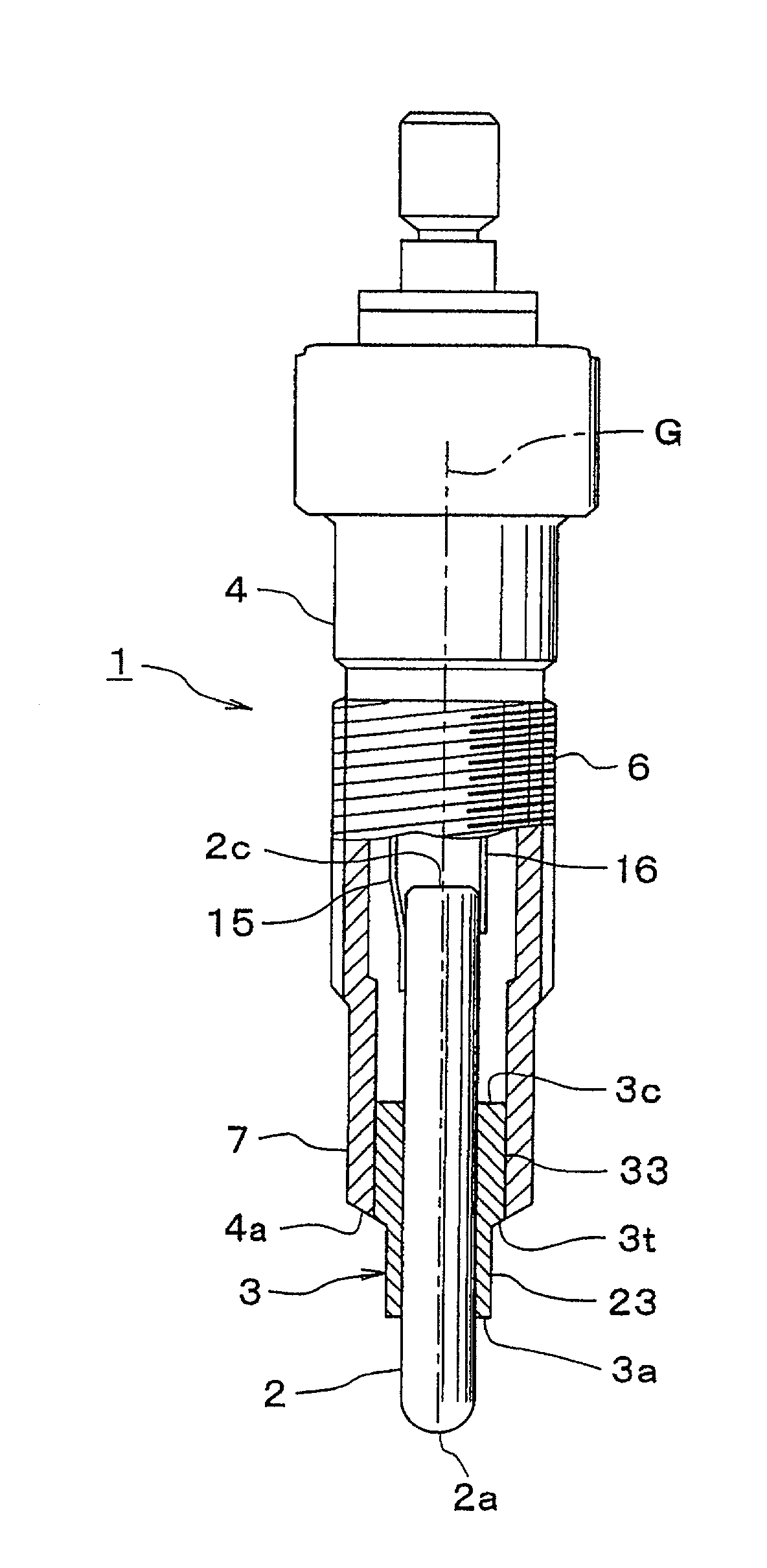
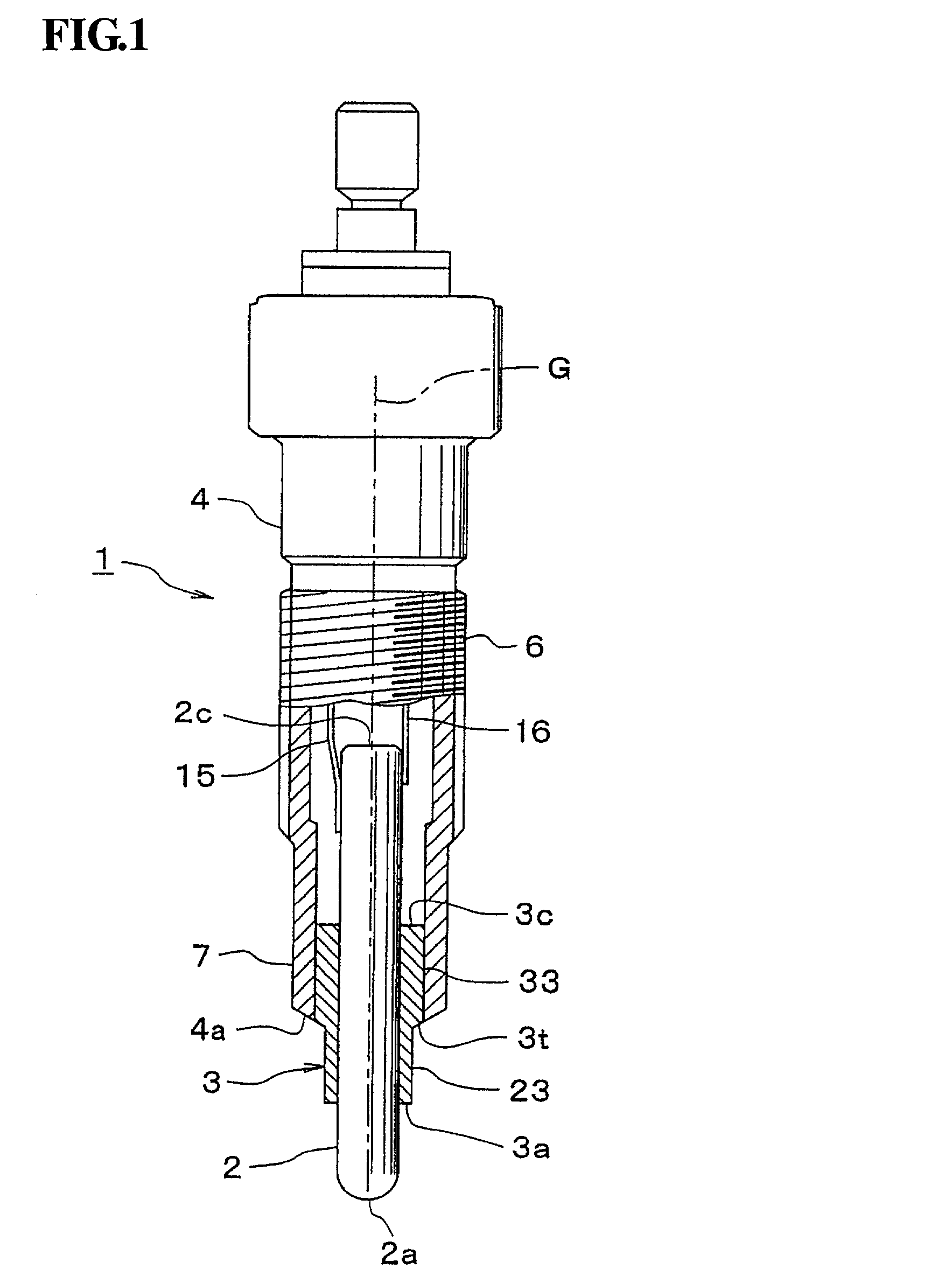
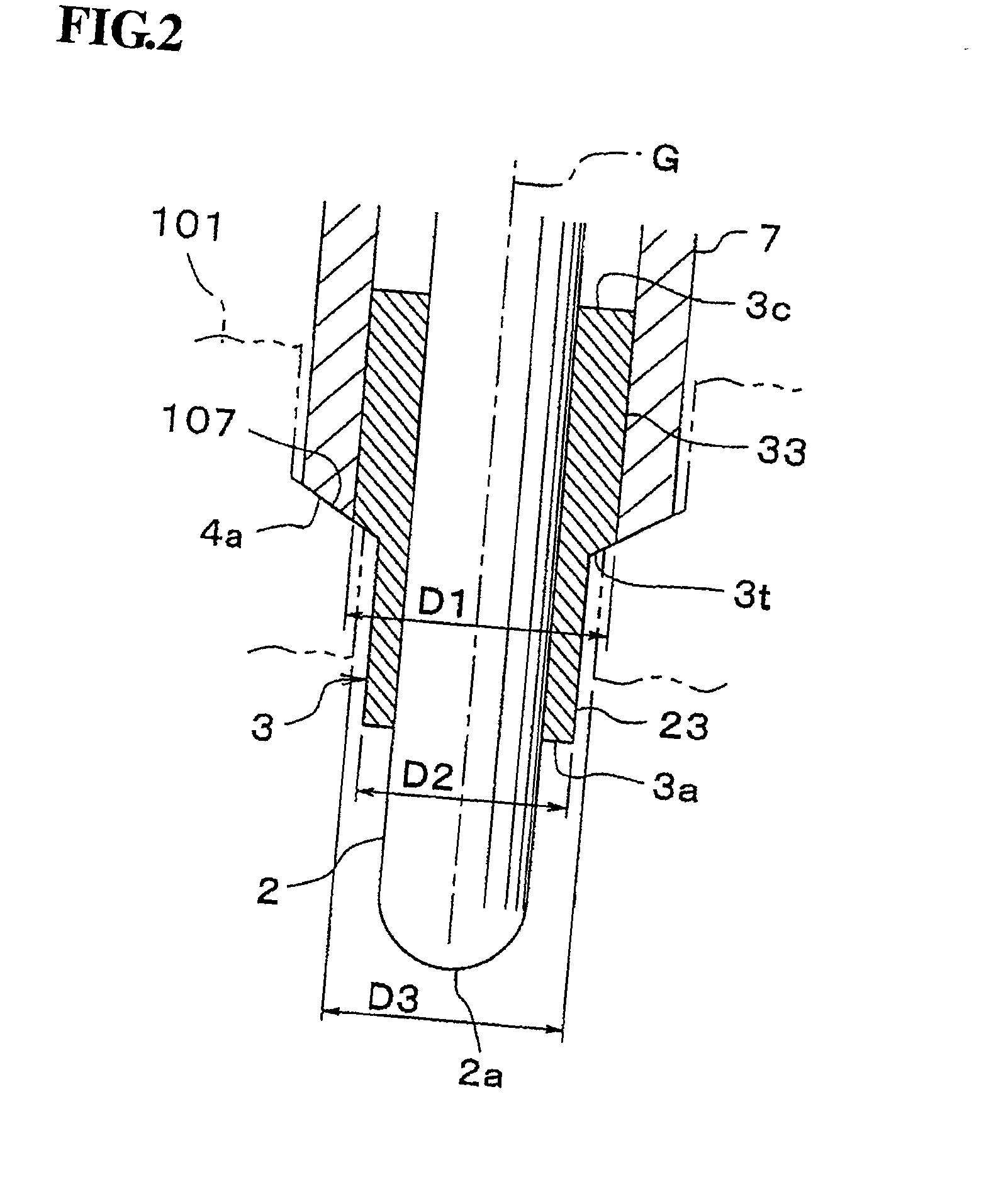
[0057] A first embodiment of the present invention will next be described in detail with reference to FIGS. 1 to 4. In the drawings, reference numeral 1 denotes a ceramic glow plug. The ceramic glow plug 1 is configured in the following manner: a round-bar-like (columnar) ceramic heater 2 is loose fitted into the interior (a cylindrical bore) of a tubular, metallic, cylindrical member 3 such that a front end 2a projects from a front end 3a of a metallic, cylindrical member (hereinafter also referred to as a cylindrical member) 3, and a rear end 2c projects from a rear end 3c of the cylindrical member 3; and a brazing metal is interposed therebetween for fixing the two components. The ceramic heater 2 is configured such that an unillustrated heating member is embedded in a ceramic substrate formed of silicon nitride. When current is ...


PUM


Abstract

A glow plug in which a ceramic heater is fixedly disposed in a metallic, cylindrical member such that a front end thereof projects from a front end of the cylindrical member, and the resultant cylindrical member is fixedly disposed in a plug body such that the front end of the cylindrical member projects from a front end of the body, and which readily provides a mounting structure such that, even when loosening arises at a joint between the body and the cylindrical member after the glow plug is mounted onto a cylinder head, the cylindrical member is prevented from dropping into the interior of an engine. A portion 23 of a cylindrical member 3 projecting from a front end 4 of a plug body 4 has outside diameter D2, which is defined as a smaller diameter than a portion of the metallic, cylindrical member which is fixedly disposed within the metallic, cylindrical plug body (a large-diameter portion 33 of the cylindrical member 3). A front-end-oriented end face 3t is formed in a diameter transition region where the outside diameter changes between the two diameters. In a mounting bore formed in a cylinder head, bore diameter D3 of a dead end portion, against which the front end 4a of the body 4 is pressed, is rendered smaller than outside diameter D1 of a large-diameter portion 33 of the cylindrical member 3. Since the dead end portion prevents movement of the cylindrical member 3, even when the cylindrical member 3 comes off the body 4, the member 3 does not drop into the interior of an engine.

Description

BACKGROUND OF THE INVENTION[0001] 1. Field of the Invention[0002] The present invention relates to a ceramic glow plug used for accelerating start-up of a diesel engine or a like application.[0003] 2. Description of the Related Art[0004] FIG. 9 shows a ceramic glow plug 1 for use in a diesel engine. The ceramic glow plug 1 is configured in the following manner: a round-bar-like (columnar) ceramic heater 2 is fixedly fitted into the interior (cylindrical bore) of a straight tubular, metallic, cylindrical member 3 such that a heater end 2a projects from a front end 3a of the metallic, cylindrical member (hereinafter may be referred to as merely a cylindrical member) 3; and the resultant assembly consisting of the ceramic heater 2 and the cylindrical member 3 is fixedly fitted into (united with) a metallic, cylindrical plug body (hereinafter also referred to as merely a plug body or body) 4 such that the front end 3a of the cylindrical member 3 projects from a front end 4a of the body ...

Claims


Application Information

Patent Timeline
IPC IPC(8): F02F1/24F02P19/00F23Q7/00
CPCF23Q7/001
Inventor TANIGUCHI, MASATOOTANI, TAKAYUKI
Owner NGK SPARK PLUG CO LTD
Why Eureka
Try Eureka