Method and apparatus for identifying software components using object relationships and object usages in use cases
a software component and object relationship technology, applied in the field of method and apparatus for identifying software components using object relationships and object usages in use cases, can solve the problems of obscure criteria and procedures for identifying components, lots of non-measurable properties of domain information,
- Summary
- Abstract
- Description
- Claims
- Application Information
AI Technical Summary
Problems solved by technology
Method used
Image


Examples
first embodiment
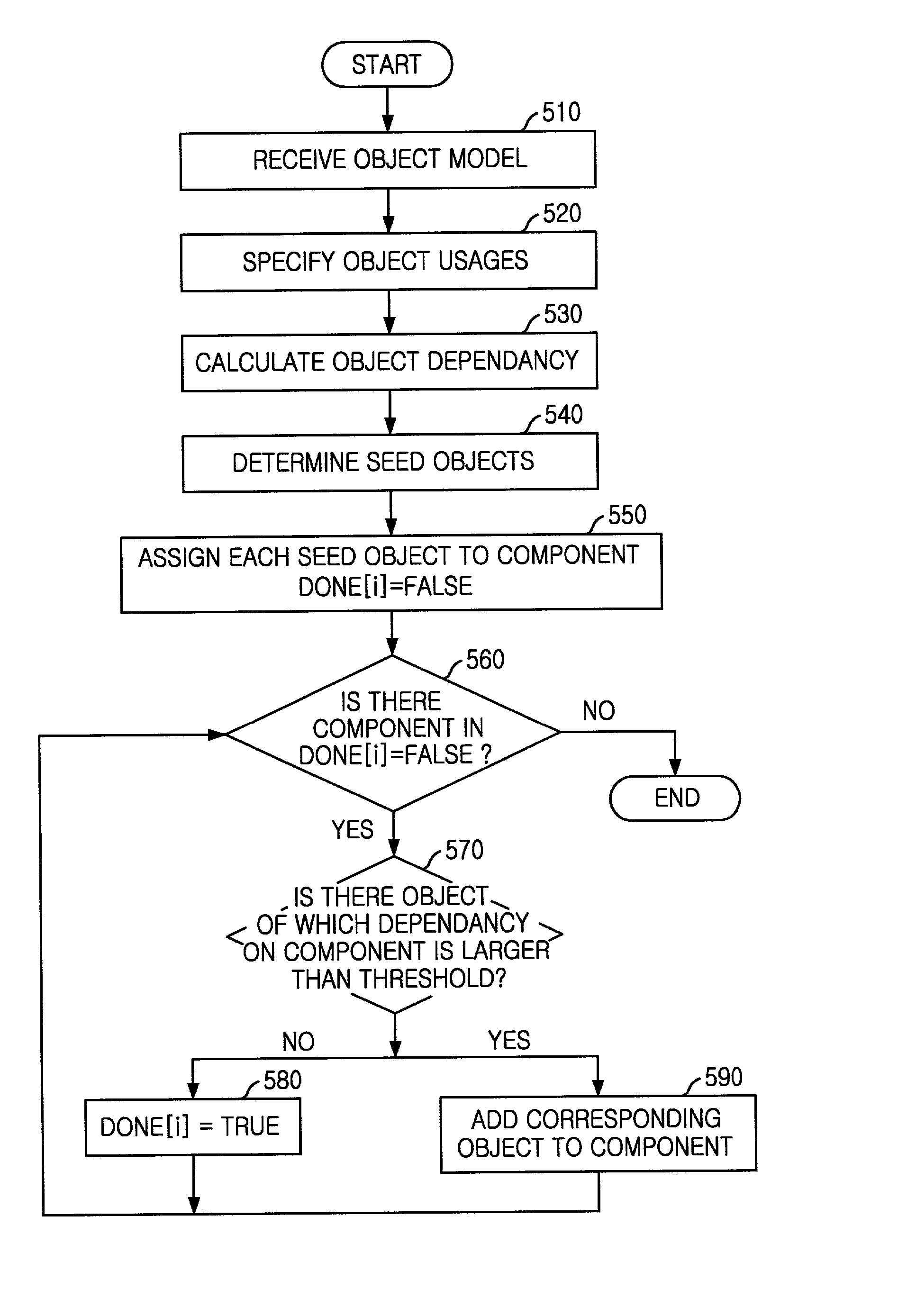
[0021] FIG. 2 is a diagram showing a use case & object dependency graph in accordance with the present invention.
[0022] As described in FIG. 2, objects 220 to 224 and use cases 210 and 211 are denoted as nodes. Dependency relationships between objects or between use cases and objects are described by seven (7) dependency keywords as following; generalization, decomposition, create&destroy, create, destroy, update, reference.
[0023] The use cases 210 and 211 and the objects 220 to 224 are described as nodes in the shapes of dotted circles and lined circles. The dependencies between the nodes are divided into a structural relationship such as a generalization 230 and accumulated object usages information such as create & destroy 231 to 233 and update+reference 235, which are obtained by adding all usages of the corresponding object in all use cases. Further, real number values 240 and 241 appeared beside of the use case nodes, which represent the weight values of the use cases and rang...
second embodiment
[0024] FIG. 3 is a diagram showing an object dependency network in accordance with the present invention. The object dependency network includes object nodes and dependencies between objects, which are denoted as dependency degrees (DD) and importance degree (ID) for each object without including use case nodes.
[0025] As described in FIG. 3, dependency degrees 321 to 324 among objects 311 to 315 have real values ranged from 0.0 to 1.0, which are calculated by using weights of use cases, inter-object structural relationships and object usages information, shown in the use case & object dependency graph.
[0026] An example of a weight-mapping table, which changes a dependency type to a dependency value ranged from 0.1 to 1.0, is shown in Table 1.
1 TABLE 1 Dependency Type (DT) Weight (DT) Aggregation 1.0 Decomposition 1.0 Create / Destroy 0.9 Create 0.7 Destroy 0.6 Update 0.5 Reference 0.3
[0027] Each value of DD between objects can be obtained by equation (1) as following. DD is obtained b...
third embodiment
[0030] FIG. 4 is a block diagram showing an apparatus of identifying software components in accordance with the present invention.
[0031] As described in FIG. 4, the component identification apparatus according to the present invention includes a graphical user interface (GUI) 410 which receives the inter-object information for the object model, the object usage information, which may be extracted from sequence diagrams or be inputted by users, a component identification threshold (CIT) and a seed object threshold (SOT) from a user. A weight calculator 420 calculates the inter-object dependency weight by using the received object dependency and object usages information from the GUI 410. An object network generator 430 generates an object dependency network by using the inter-object dependency weights calculated in the weight calculator 420. Based on CIT and SOT received from GUI, a component identifier 440 controls a component identification process by using the object dependency ne...
PUM
 Abstract
Description
Claims
Application Information
 - R&D
- Intellectual Property
- Life Sciences
- Materials
- Tech Scout
- Unparalleled Data Quality
- Higher Quality Content
- 60% Fewer Hallucinations
Browse by: Latest US Patents, China's latest patents, Technical Efficacy Thesaurus, Application Domain, Technology Topic, Popular Technical Reports.
© 2025 PatSnap. All rights reserved.Legal|Privacy policy|Modern Slavery Act Transparency Statement|Sitemap|About US| Contact US: help@patsnap.com