
System and method for generating a database of pulse characteristics for each pulse of an acquired signal in a signal measurement system

a signal measurement system and database technology, applied in the field ofsignal measurement systems, can solve the problems of inability to define a trigger condition for an anomaly, the operator's management of the display and measurement of such a large number of pulses is considerable, and the sample consumes 1 byte of memory

Inactive Publication Date: 2002-09-12
AGILENT TECH INC
View PDF0 Cites 20 Cited by
  • Summary
  • Abstract
  • Description
  • Claims
  • Application Information

AI Technical Summary

Problems solved by technology

Typically, an 8-bit analog-to-digital (A / D) converter is implemented, resulting in each sample consuming 1 byte of memory, although other conventional systems implement a 16-bit A / D converter.
Managing the display and measurement of such a large number of pulses presents a considerable challenge to the oscilloscope operator.
Typically, the number of anomaly is unknown, so defining a trigger condition for the anomaly is not possible.
Due to a limited size and resolution of the oscilloscope's display, only a small number of pulses may be accessed simultaneously at a horizontal scaling sufficient for accurate characterization.
Analyzing all the pulses of a given acquisition this way requires the operator to manually advance through the data a few pulses at a time, a prohibitively time-consuming process.
As a result, operators of conventional systems are limited to accessing only a small subset of the pulses, generally, in an ad hoc or unstructured maimer.
This reduces the likelihood that the operator of a conventional deep memory oscilloscope will successfully identify anomalous pulses efficiently.
Some conventional systems include facilities for determining measurement statistics, however, in such implementations, the statistics are accumulated from measurements performed over multiple acquisitions and / or the results are computed such that a given measurement value is not readily traceable to the pulse it is associated with.
Accumulating statistics over multiple acquisitions is disadvantageous because the acquisitions may relate to different operating conditions in the circuit or system being analyzed.
Additionally, depending on how many pulses are measured from each acquisition, the tine spacing between measured pulses may vary significantly, making statistical understanding less straightforward.
When statistics are computed without traceability to individual pulses, the operator is unable to view the particular pulse associated with the given measurement result.
Without a view of the pulse, the operator is at a loss to determine when caused the measurement result.
In sum, in currently available signal measurement systems, it is difficult for an operator to characterize or troubleshoot a system or circuit through analysis of the large number of pulses that may be captured in a single acquisition.
Due to the many thousands of operator actions that would be necessary to invoke a number of traditional pulse measurements on the perhaps thousands of acquired pulses, there has been no attempt heretofore to provide any structure for storing or organizing such measurement data.
Due to the many thousands of operator actions that would be necessary to invoke a number of traditional signal pulse measurements on the perhaps thousands of acquired pulses, there has been no attempt heretofore to provide any structure for storing or organizing such measurement data.

Method used


Image

  • System and method for generating a database of pulse characteristics for each pulse of an acquired signal in a signal measurement system
  • System and method for generating a database of pulse characteristics for each pulse of an acquired signal in a signal measurement system
  • System and method for generating a database of pulse characteristics for each pulse of an acquired signal in a signal measurement system

Examples


Embodiment Construction

[0072] A. High-Level Description

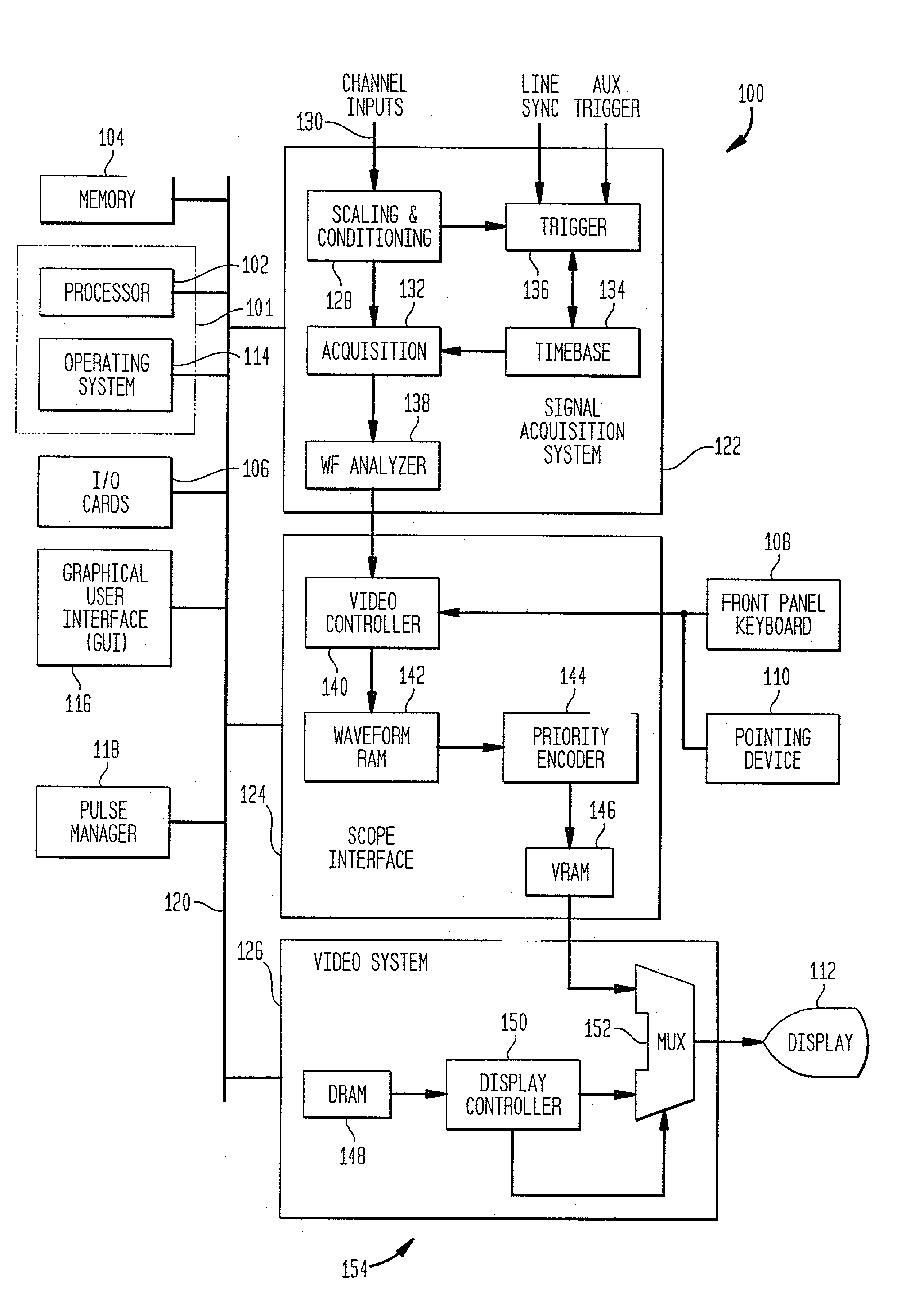
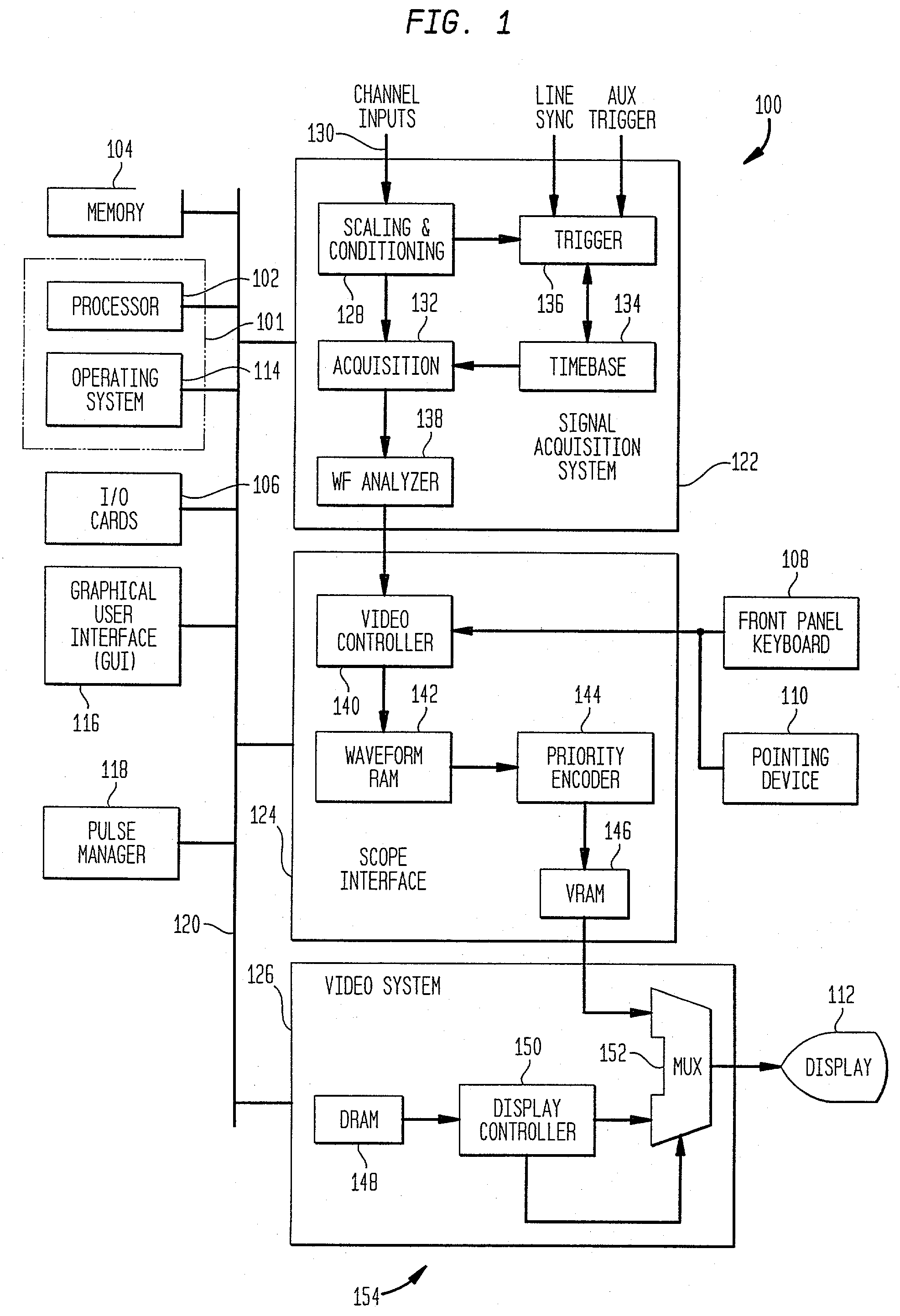
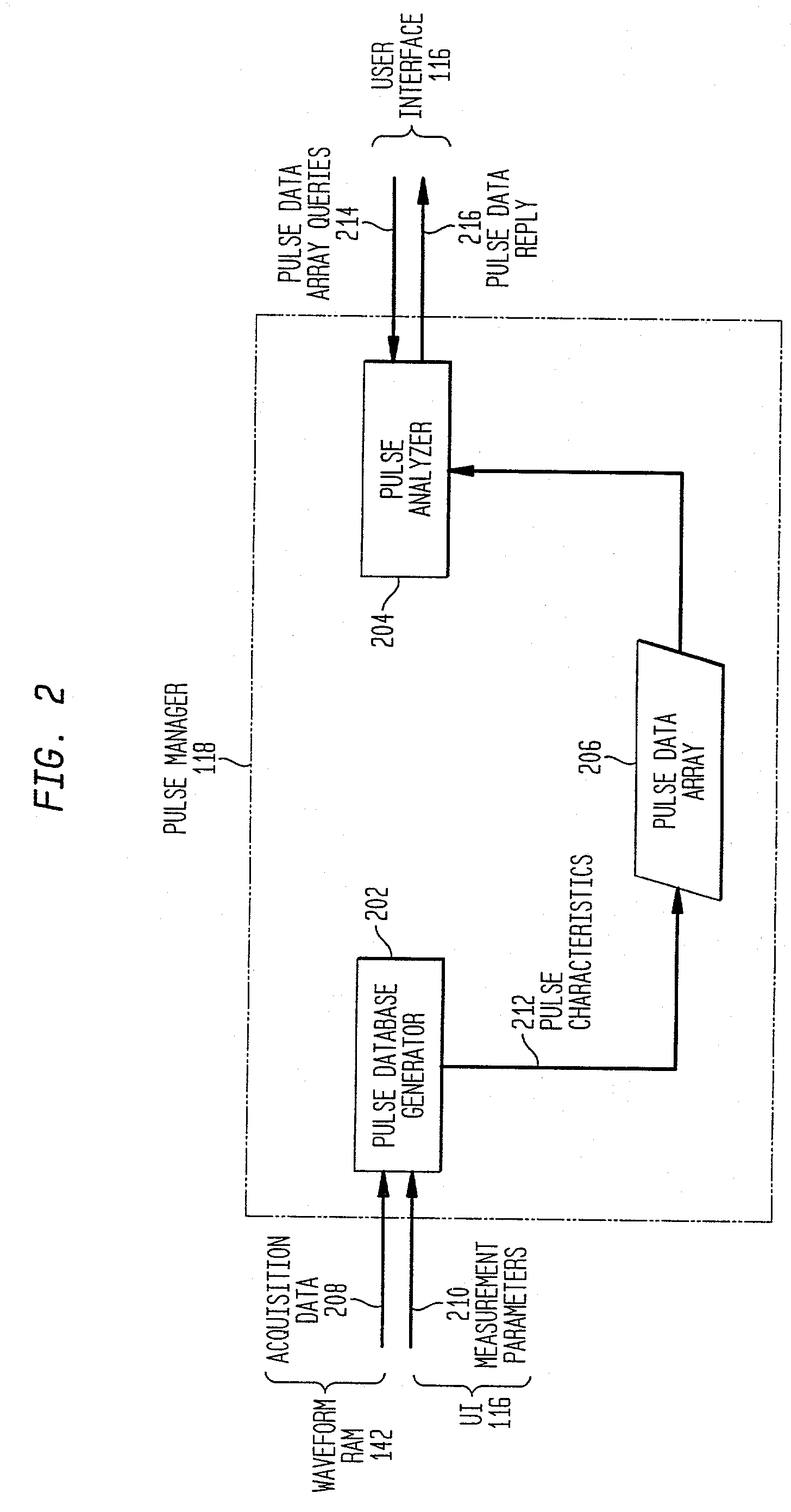
[0073] A high-level functional block diagram of one embodiment of pulse manager 118 implemented in digital oscilloscope 100 is shown in FIG. 2. Pulse manager 118 has access to acquisition data 208 stored in an acquisition memory that is part of acquisition block 132 illustrated in FIG. 1. A preferred implementation of pulse manager 118 operates with a user interface such as graphical user interface 116 to receive measurement parameters 210 to guide the pulse measurements and to provide a graphical interactive environment in which the operator can manipulate or otherwise analyze the pulse characteristics 212 stored in pulse data array 206.

[0074] Generally, pulse manager 118 comprises two primary operational components and a novel data structure of pulse characteristics 212. A pulse database generator 202 performs, with minimal or no operator involvement, a series of one or more pulse measurements on acquired data 208 stored in acquisition memory. The r...


PUM


Abstract

A pulse management system for use by an operator that automatically performs measurements on a subset of pulses of an acquired signal stored in an acquisition memory, and generates an accessible data structure that stores characteristics of the chosen subset of acquired signal pulses, including pulse measurement results. The system searches the data structure for pulses of the acquired signal that satisfy operator-provided search criteria. In addition, the operator can sort the selected pulses in any desired manner by specifying a desired sort criteria. The system displays selected pulses along with the associated measurement results, and enables the operator to advance through the selected pulses in any manner desired to display different pulses together or separately along with the associated pulse measurement results. A method for analyzing pulses of an acquired signal is also disclosed. The method includes the step of generating a pulse data array having stored therein pulse characteristics of a previously acquired signal, followed by the step of analyzing the contents of the pulse data array in response to operator specifications.

Description

[0001] The present application is related to the following commonly owned applications which are hereby incorporated by reference herein in this application: U.S. Application entitled "System and Method For Enabling an Operator to Analyze a Database of Acquired Signal Pulse Characteristics" naming as inventor Jay A. Alexander, and filed concurrently herewith under Attorney Docket No. 10004118-1; and[0002] U.S. Application entitled "Voice-Responsive Command and Control System and Methodology For Use In A Signal Measurement System" naming as inventors Jay A. Alexander and Michael Karin, filed on Aug. 30, 1999 under attorney docket number 10961062-1.[0003] 1. Field of the Invention[0004] The present invention relates generally to signal measurement systems and, more particularly, to managing a large number of acquired pulses in a signal measurement system.[0005] 2. Related Art[0006] Conventional signal measurement systems such as digital oscilloscopes sample, record and display time-va...

Claims


Application Information

Patent Timeline
Patent Type & Authority Applications(United States)
IPC IPC(8): G01R13/34G06F19/00G01R13/00G01R29/02
CPCG01R13/345G01R29/02Y10S707/99945Y10S707/99948
Inventor ALEXANDER, JAY A.
Owner AGILENT TECH INC
Learn More