Head, recording apparatus having the head, method for identifying the head, and method for giving identification information to the head
a recording apparatus and head technology, applied in the field of recording heads, can solve the problems of increasing the cost of recording heads and printing apparatuses, reducing reliability, and increasing costs, and achieve the effect of simple manufacturing process
- Summary
- Abstract
- Description
- Claims
- Application Information
AI Technical Summary
Benefits of technology
Problems solved by technology
Method used
Image

Examples
first embodiment
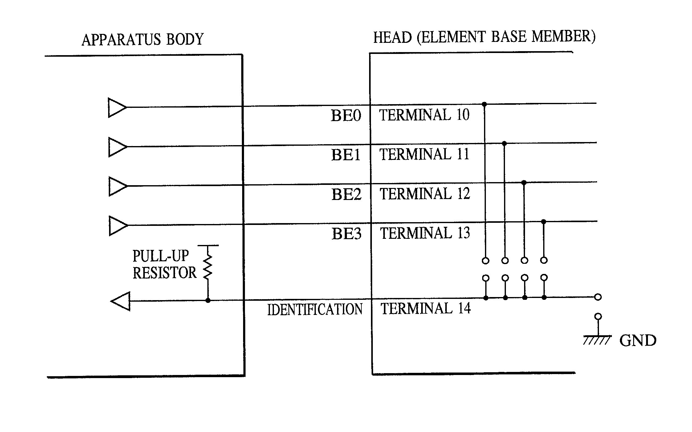
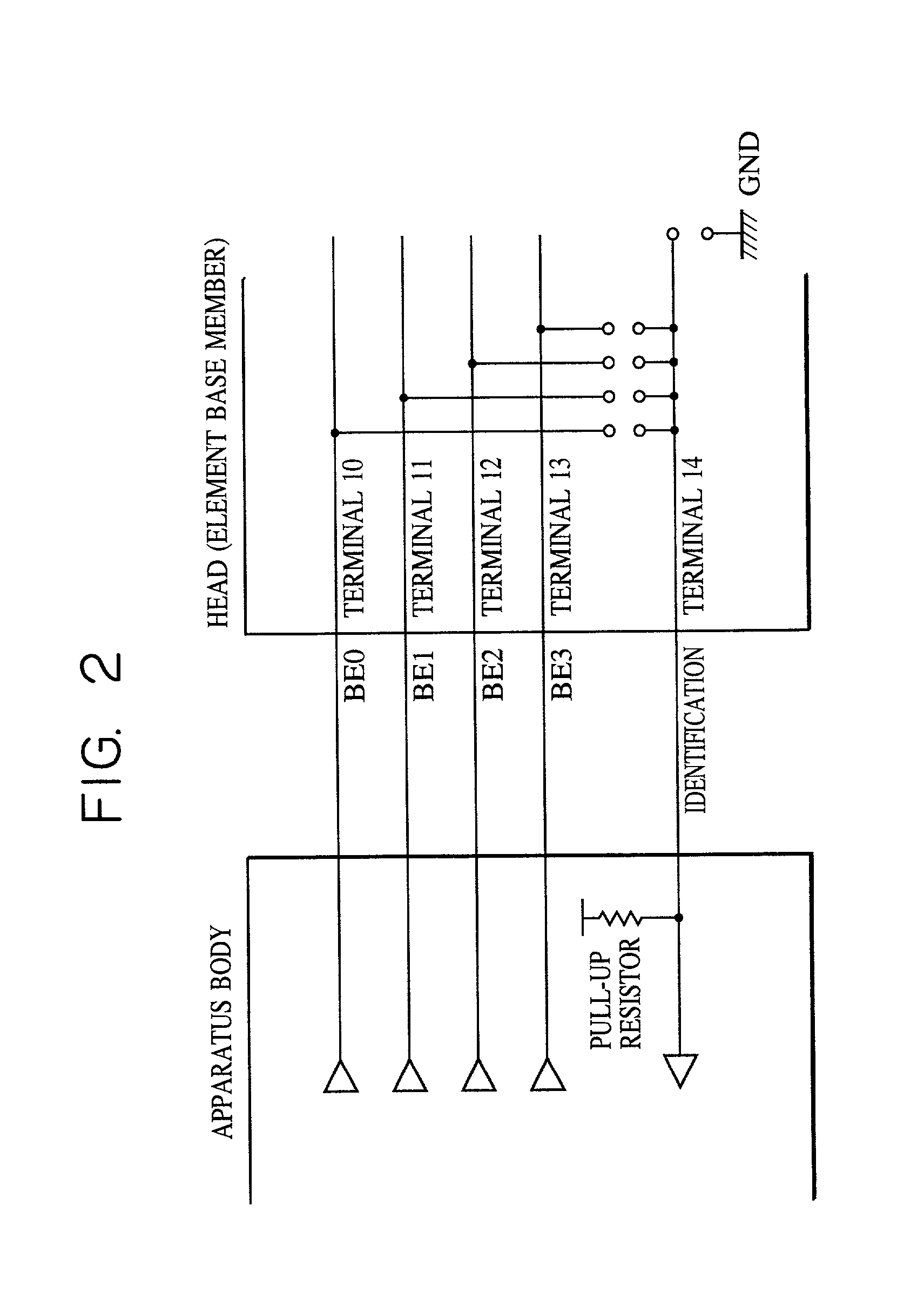
[0052] FIG. 2 is a view used for describing connections between an apparatus body and the identification circuit of a head according to an embodiment of the present invention.
[0053] FIG. 3 shows an arrangement of press-fit pads serving as driving terminals and identification terminals for connection between the head in which the circuit shown in FIG. 2 is built and the apparatus body. Since the head is provided with three element base members, three types of pads are prepared for a Data1 terminal, a Data2 terminal, a HE terminal, an SHE terminal, a Rank terminal, a Di1A terminal, and a Di2A terminal, each for an A chip, a B chip, and a C chip.
[0054] FIG. 4 is a logic diagram of an element base member of the head in which the circuit shown in FIG. 2 is built-in the element base member.
[0055] This bubble-jet printing head has two columns (SEG0 to SEG255) of 128 heaters (segments). As described before, nozzles having paths and discharge outlets are provided correspondingly to the heate...
second embodiment
[0065] FIG. 7 is a logic diagram which differs from that shown in FIG. 4 in that the output of the decoding circuit is connected to the identification terminal 14. With this connection, the states of the fourth power of 2 plus 2 (a total of 18) can be identified although only the BE0 terminal 10 to the BE3 terminal 13 are used as signal terminals in the same way as in the first embodiment. Signals are output from the four terminals, the BE0 terminal 11 to the BE3 terminal 13, at the same time, and a signal level is changed sequentially at each terminal to send 16 types of signals. In the present embodiment, since n driving terminals are connected to the identification terminal through the decoding circuit in the head, when a signal is sent through one or more driving terminals at the same time, the terminal through which a signal is sent is sequentially changed, and the signal is read each time, the types of the n-th power of 2 plus 2 can be identified with a case in which a line is...
third embodiment
[0067] In the above embodiments, one identification terminal is used. A plurality of identification terminals may be used.
[0068] If two identification terminals are used in the first embodiment, since six types can be identified by one identification terminal, 36 types (six multiplied by six) can be identified.
PUM
 Abstract
Description
Claims
Application Information
 - R&D
- Intellectual Property
- Life Sciences
- Materials
- Tech Scout
- Unparalleled Data Quality
- Higher Quality Content
- 60% Fewer Hallucinations
Browse by: Latest US Patents, China's latest patents, Technical Efficacy Thesaurus, Application Domain, Technology Topic, Popular Technical Reports.
© 2025 PatSnap. All rights reserved.Legal|Privacy policy|Modern Slavery Act Transparency Statement|Sitemap|About US| Contact US: help@patsnap.com