
Carburetor throttle and choke control mechanism

a technology of choke control mechanism and carburetor, which is applied in the direction of electrical control, heating types, separation processes, etc., can solve the problems of choke valve sometimes not being completely closed, failure in practice, and much to be desired

Inactive Publication Date: 2002-09-05
WALBRO LLC
View PDF0 Cites 25 Cited by
  • Summary
  • Abstract
  • Description
  • Claims
  • Application Information

AI Technical Summary

Benefits of technology

The solution ensures consistent and complete closure of the choke valve, improving cold engine starting performance without increasing production costs or altering existing manufacturing processes, and is adaptable to both twistable and non-twistable choke shafts, as well as split linkage carburetors.

Problems solved by technology

Prior to the late 1970s, chain saws equipped with such choke and throttle controls often involved a basic starting sequence which left much to be desired.
One of the disadvantages of this fast idle starting system (FISS) '480 patent design was its failure in practice when mass produced to insure complete and / or consistent closure of the choke valve 10 when setting the fast idle latch starting system.
The specific problem has been found to be due to a pull-back or rock-back effect by the fast idle lever exerted on the choke lever resulting in the choke valve sometimes not being completely closed even though the operator has fully engaged the choke control to indicated start position.
Further, it has been found that this problem is due to the need to provide an "over-travel" gap in the resting engagement of throttle lever tang in the fast idle lever notch to accommodate a stack up of normal manufacturing tolerances in the parts as manufactured for assembly into the fast idle latch mechanism.
This is a particular problem in producing carburetors for engines for chain saws, lawn mowers, clearing saws, weed whips, etc. that require very low manufacturing cost due to the low retail price of such consumer products.
The problem is compounded due to the small size of the carburetors for such small engines, and the corresponding minuscule size of the choke and throttle parts involved in the carburetor mechanisms.
These factors make it particularly difficult to reduce manufacturing tolerance allowances in order to reduce the adverse effects of unavoidable manufacturing dimensional variations in such tiny parts when assembled for operation in the mechanism.
Thus, in the case of the incomplete and / or inconsistent closure of the choke valve in the operation of the fast idle starting system of the '480 patent arrangement, it has been found that, without the aforementioned over-travel gap allowance, a shift in tolerances for all parts (tolerance stack-up) in the latch mechanism to one end limit will render the choke valve incapable of reaching the fully closed position.
This results in a loss of function of the entire choke throttle fast idle system.
Thus, the aforementioned prior art '118 and '480 patents neither address the problems nor provide a solution thereto that insures that, in the case of the '480 type fast idle start mechanism, as manufactured in mass production practice, the choke will be able to reach the fully closed position at fast idle latch-up.
Therefore, the problems of poor starting, or in worst case, "no starting", continued to prevail for many years despite the wide spread use of the '480 system on carburetors supplied by several major carburetor manufacturers utilizing the '480 system.
However, due to part variability, the advancement from tooth to tooth may not be smaller than the over-travel, and hence the choke valve can in such cases still be pulled off full choke for such over-travel, albeit a small amount.
Another limitation of this Pattullo system is that the choke shaft must be made of a flexible material, such as the plastic material specified in the Pattullo application, for this design to function properly.
However, these detent systems add cost, and in any event are not easily used in conjunction with a FISS because they do not generate enough force to overcome the rock-back forces produced by the powerful throttle valve spring.

Method used


Image

  • Carburetor throttle and choke control mechanism
  • Carburetor throttle and choke control mechanism
  • Carburetor throttle and choke control mechanism

Examples


first embodiment

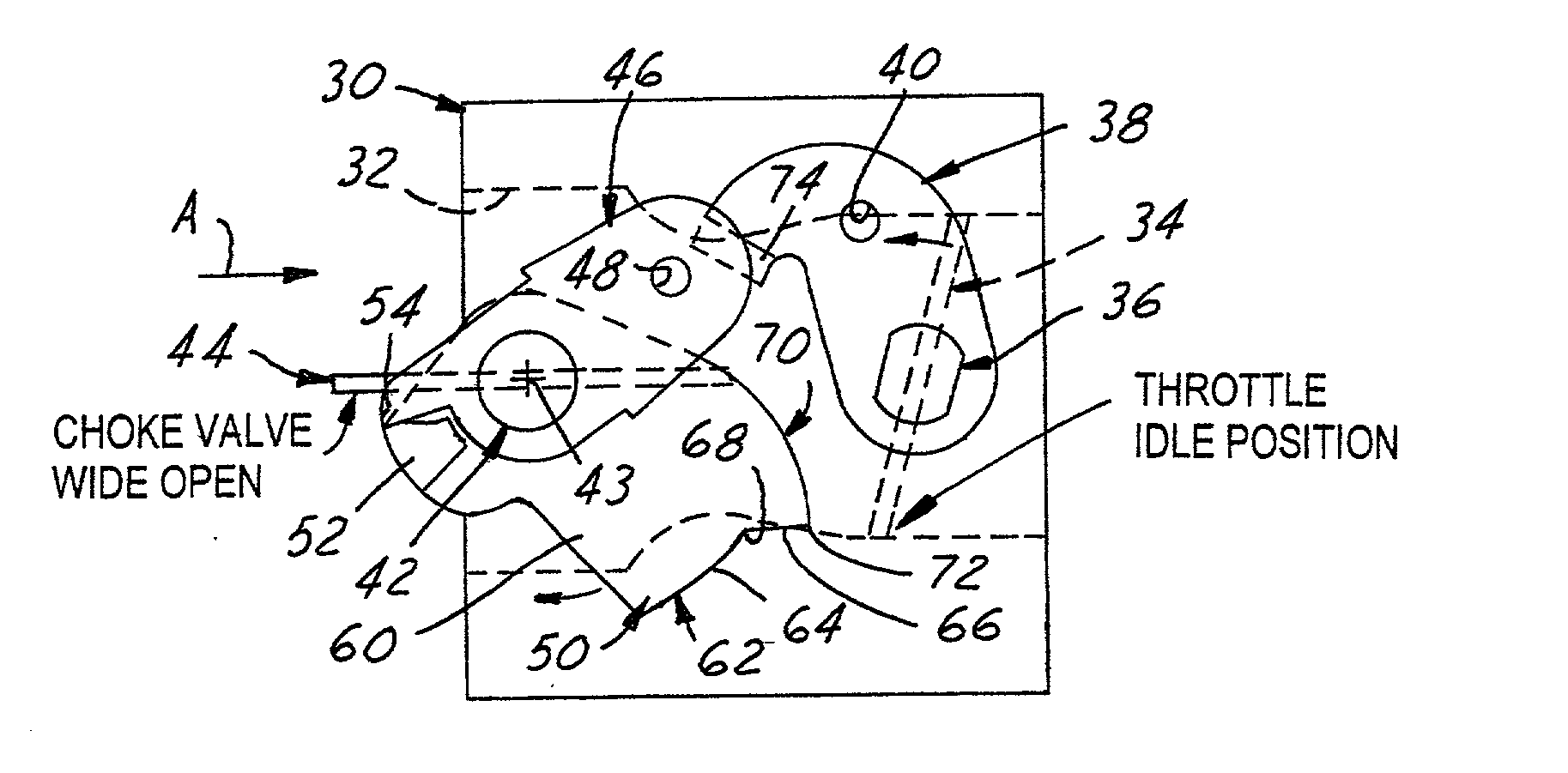
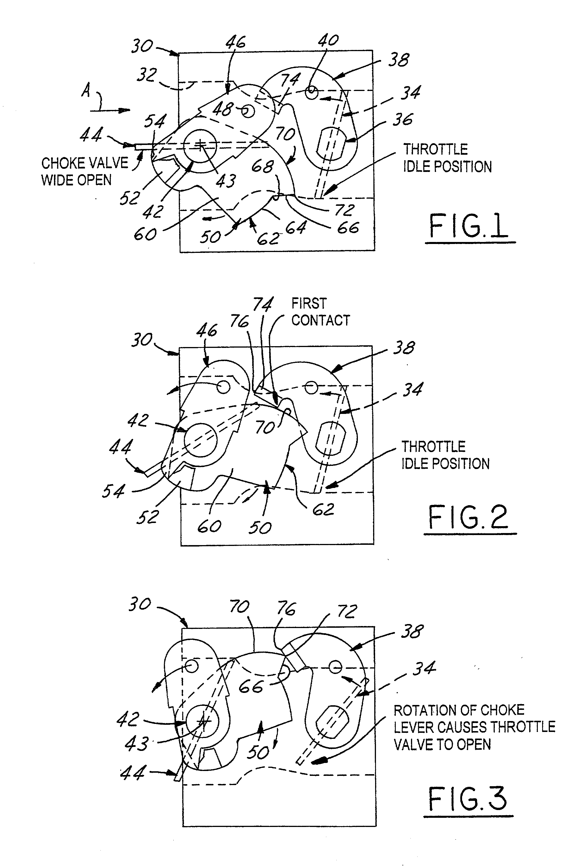
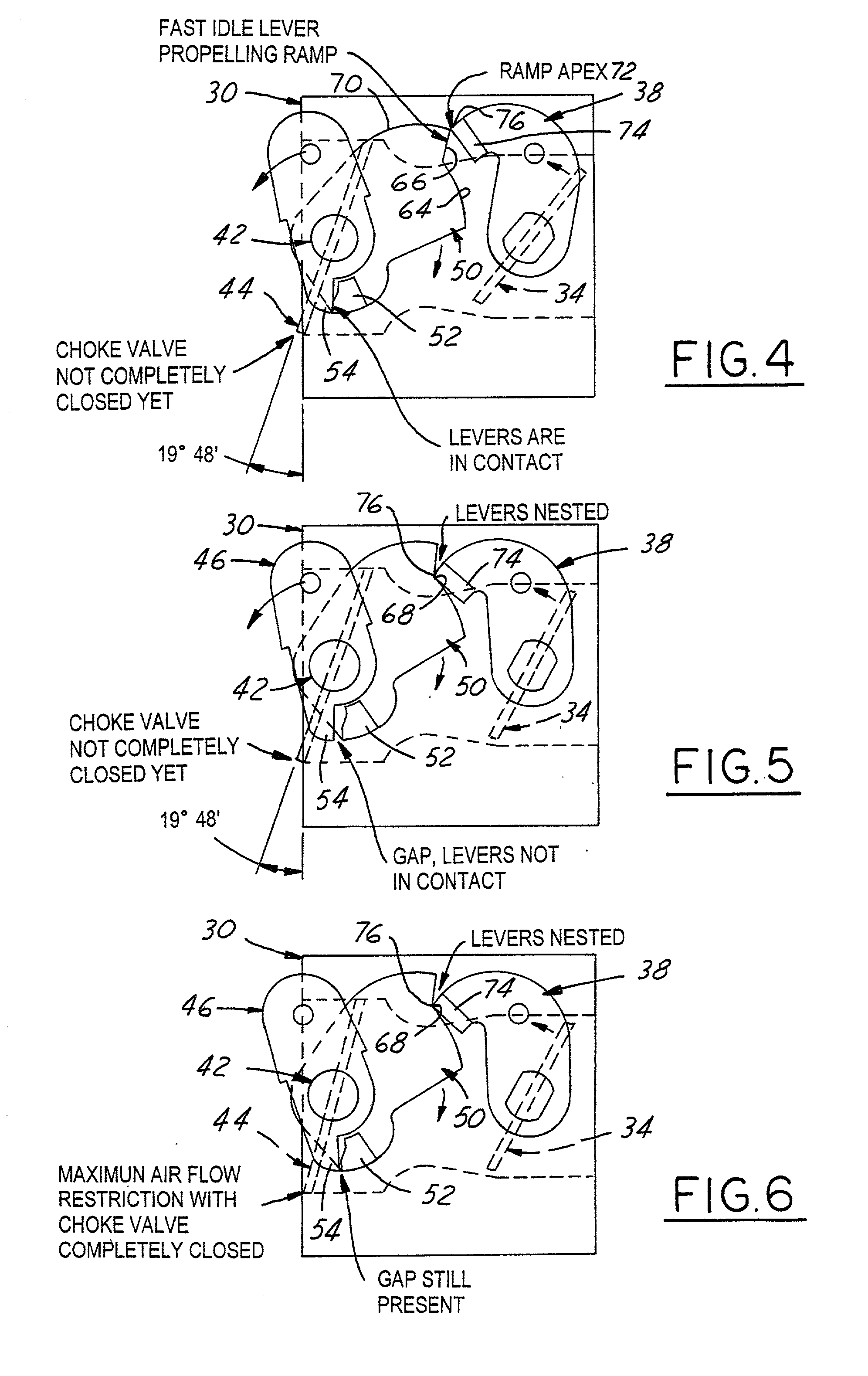
[0033] Referring in more detail to the accompanying drawings, FIGS. 1 through 8 illustrate the principal operative components of a first embodiment of the improved throttle-choke automatic fast idle throttle setting mechanism of the invention. The system of FIGS. 1-8 employs some of the same component parts and operates generally in the same, albeit improved, manner as the Johansson '480 patent construction described as prior art in conjunction with FIGS. 8-13 of the aforementioned Van Allen U.S. Pat. No. 6,000,683. Thus, the first embodiment automatic latch mechanism of the invention is well adapted for installation in and on a modem small engine carburetor 30 of conventional well-known construction. Accordingly, the structure, function and mode of operation of carburetor 30 will be understood by those skilled in the art from the views of FIGS. 1-8 and thus for brevity is not further described herein.

[0034] More particularly and referring to FIGS. 1-8, it will be seen that carburet...

second embodiment

[0052] The second embodiment of the invention as illustrated in FIGS. 9, 10 and 11, wherein the only change in component parts is that of the modified choke lever denoted 146 in these views. Choke lever 146 is constructed and mounted on choke shaft 42 in the same manner as choke lever 46 except for the modification of the pusher end of the choke lever. The pusher foot 54 of lever 46 is replaced by a flexible engagement hook portion 154 that is operable when the parts have been conditioned to the fast idle start position of FIG. 9 to pull and hold the choke valve closed when in its latched-up condition shown in FIG. 9. Preferably the choke lever hook 154 is molded as an integral portion of the choke lever 146 when the same is preferably made out of the material specified in the aforementioned co-pending Pattullo application, namely a resilient and flexible plastic material such as Delrin.RTM. acetal plastic. This is the material of the choke shaft disclosed in this co-pending applica...

third embodiment

[0057] As indicated previously, FIGS. 16, 17 and 18 are simplified diagrammatic views of a third embodiment "split linkage" carburetor equipped with a first embodiment type rigid choke shaft 42 and rigid choke lever split up into two separate components comprising a crank arm part 246 and a pusher foot part 346. The crank arm 246 is fixed to one end of choke shaft 42 on one side of the carburetor, whereas the pusher part 346 is fixed to the axially opposite end of choke shaft 42 on the other side of the carburetor. The remaining components of the FISS third embodiment system are the same as in the first embodiment system, and it will be seen that the mode of operation is also the same in both embodiments.


PUM

PropertyMeasurementUnit
choke valve angleaaaaaaaaaa
torqueaaaaaaaaaa
torsionally resilientaaaaaaaaaa

Abstract

A carburetor throttle and choke control mechanism incorporating a choke-throttle cold-start fast idle setting latch mechanism having, in a first embodiment, a blade of a fast idle lever specially contoured for creating upon interengagement with a tang on a throttle lever initial torque resistance to co-rotation of the fast idle lever toward latched condition and then effecting force reversal for creating aiding torque to accelerate the fast idle lever relative to choke lever and thereby open a gap in the push coupling that remains in the latched position of the choke and throttle valves. The choke lever has a relatively rigid pusher leg portion adapted for abutment in push relation with a fast idle lever tang. In a second embodiment an extension of the leg portion in the form of a generally U-shaped resilient spring hook portion is adapted to overlap the tang and releasably hook engage the same when the leg portion is brought into full push abutment with said tang. The U-shaped hook portion is resiliently flexible to act as a spring to develop a torque on the choke by pulling the choke valve fully closed when said fast idle lever is moved to fully latched condition while flexing so that the gap remains between the pusher leg portion and the tang.

Description

[0001] The present invention relates to throttle and choke control mechanisms of carburetors for internal combustion engines, and more particularly to such a mechanism incorporating a choke-throttle, cold-start-setting latch mechanism that automatically positions the throttle valve slightly open when the choke valve is fully closed.[0002] In small carburetors designed for use with low displacement gasoline fueled engines, such as used on chain saws, weed whips, lawn mowers, garden tractors and other small lawn, garden, and forestry portable appliances, manually operated choke and throttle controls are typical provided and often hand cranking is employed for starting the engine. Prior to the late 1970s, chain saws equipped with such choke and throttle controls often involved a basic starting sequence which left much to be desired. First the choke valve was fully closed to its start position, and then the starter rope was pulled until the engine fired. The closed choke valve usually c...

Claims


Application Information

Patent Timeline
Patent Type & Authority Applications(United States)
IPC IPC(8): F02M1/02F02M3/06F02M17/40F02M19/00
CPCF02M1/02
Inventor KING, ERIC L.PATTULLO, GEORGE M.
Owner WALBRO LLC
Learn More