
Back-up control method and apparatus for turbo machine

a turbo machine and control method technology, applied in mechanical equipment, engines, machines/engines, etc., can solve the problems of not being able to achieve advantageous use in aircraft, and the transition from electronic engine control system to back-up engine control system can be harmful to the turbo machin

Inactive Publication Date: 2002-06-27
PRATT & WHITNEY CANADA CORP
View PDF0 Cites 16 Cited by
  • Summary
  • Abstract
  • Description
  • Claims
  • Application Information

AI Technical Summary

Benefits of technology

[0014] It is another object of the present invention to provide an electronically operated back-up system for a turbo-machine that is able to guarantee a minimum fuel flow in the engine in order to avoid a flameout.
[0015] It is another object of the present invention to provide an electronically operated back-up system for a turbo-machine that is able to avoid power increase or decrease in the engine during the transfer to the back-up control mode.
[0018] According to another embodiment of the present invention, there is provided a method for determining a burn fuel flow value for an aircraft turbo-machine in case of a malfunction, the method comprising the steps of receiving a current fuel flow value from a main burn fuel flow calculator, storing the current fuel flow value prior to the malfunction, calculating a back-up burn fuel flow value using sensor readings from the aircraft and initially the stored current fuel flow value, wherein the calculating using an algorithm which is different from an algorithm used for calculating the main burn fuel value, the back-up burn fuel flow value having a smooth transition between the current fuel flow value prior to the malfunction and future burn fuel flow values and outputting the back-up burn fuel flow value to a fuel metering unit,

Problems solved by technology

Furthermore, the use of a hydromechanical back-up control increases the weight and the complexity of the control system, thus this is not an advantageous solution for a use in an aircraft.
When a failure of the electronic engine control system is detected, a sudden transition from the electronic engine control system to a back-up engine control system can be harmful to the turbo-machine.
In fact, if the fuel flow computed by the electronic engine control system at its failure is far different from the fuel flow computed by the back-up engine control system when it is enabled, great damages can occur due to a the non-continuous supply of fuel.

Method used


Image

  • Back-up control method and apparatus for turbo machine
  • Back-up control method and apparatus for turbo machine
  • Back-up control method and apparatus for turbo machine

Examples


Embodiment Construction

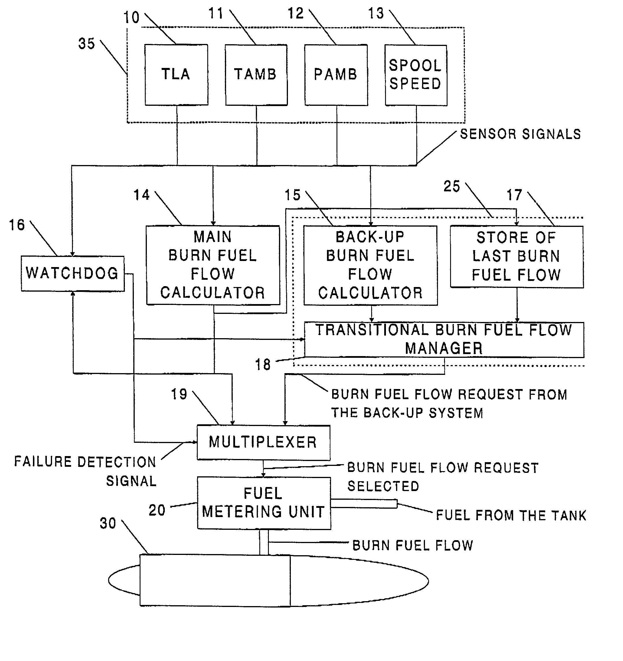
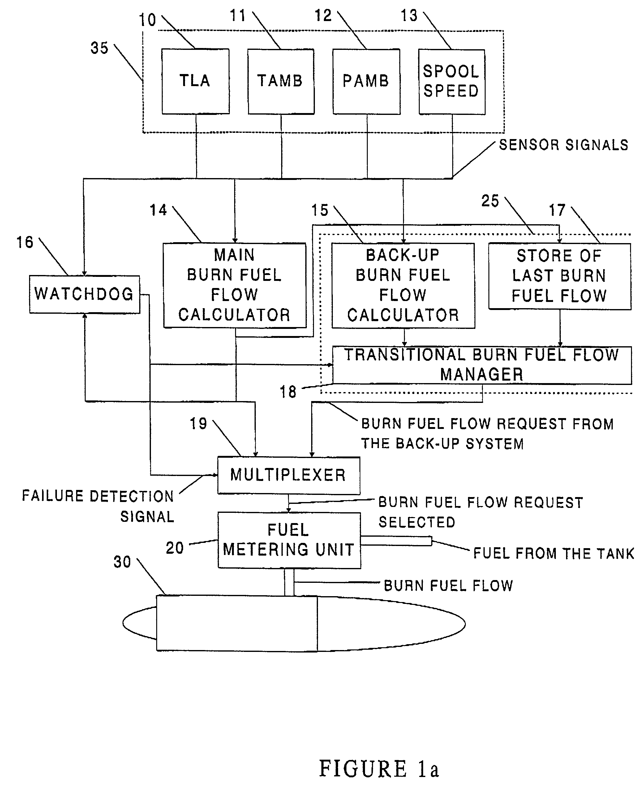
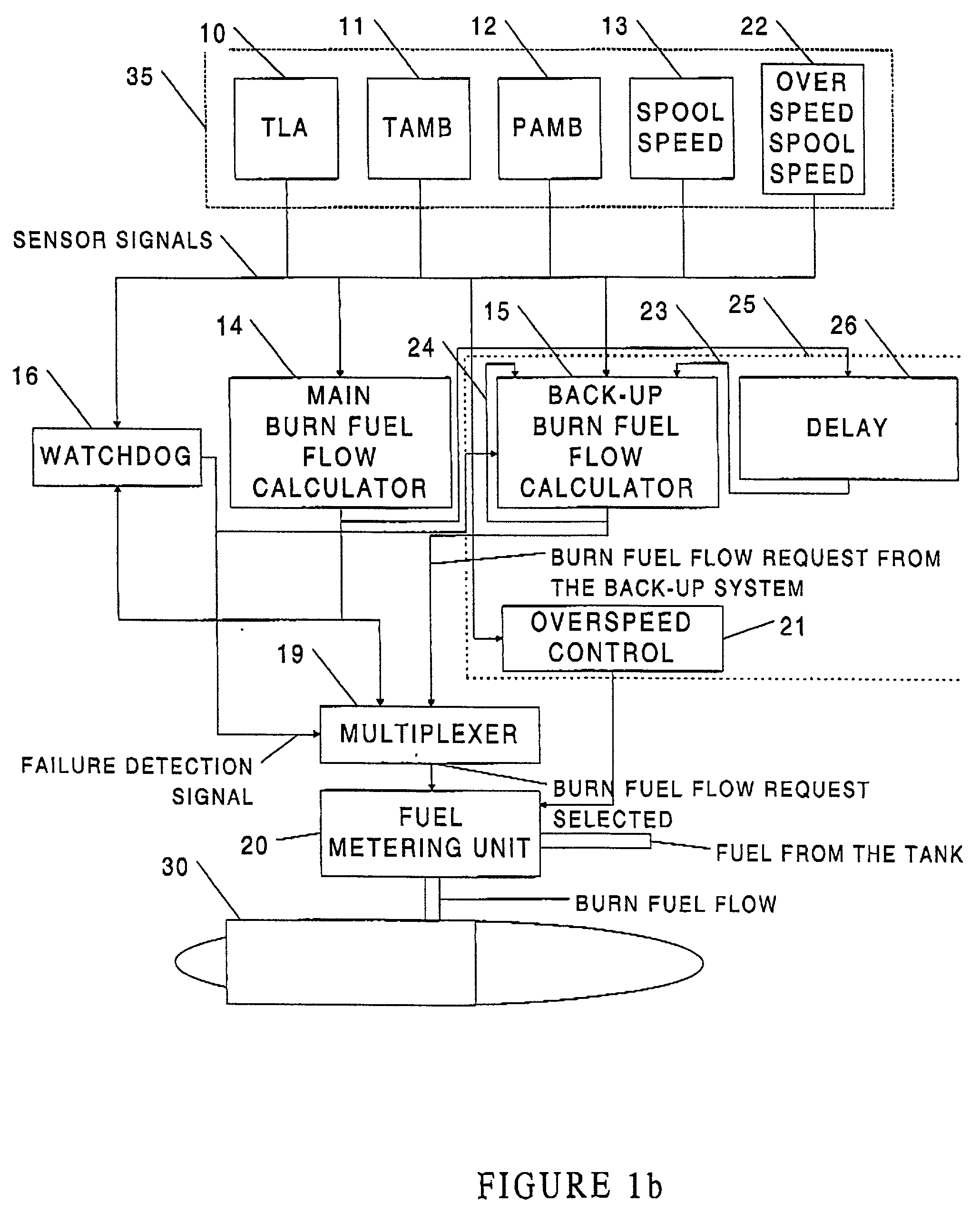
[0027] Now referring to FIG. 1a, there is shown a turbo-machine 30. This turbo-machine 30 receives fuel from a fuel metering unit 20. The fuel metering unit 20 is feeded by fuel which comes from the fuel tank of the aircraft. The fuel metering unit 20 is either driven by a main burn fuel flow calculator 14 or by a back-up control 25. In case of failure of the main burn fuel flow calculator 14, the back-up control 25 provides the burn fuel flow request to the fuel metering unit 20. Both the main burn fuel flow calculator 14 and the back-up control 25 collect information coming from a group of sensors 35. The type of information used by the main burn fuel flow calculator 14 and the back-up control 25 will be more detailed in the following description.

[0028] More precisely, and still referring to FIG. 1a, the group of sensors 35 comprises a Throttle Lever Angle (TLA) sensor 10, an ambient pressure (P.sub.Amb) sensor 12, an ambient temperature (T.sub.Amb) sensor 11 and a turbo-machine s...


PUM


Abstract

A method and apparatus for controlling a turbo-machine in case of failure of the main burn fuel flow calculator. The apparatus receives at least information from various sensors as well as from the main burn fuel flow calculator. The method and apparatus, herein disclosed, provides a smooth and secure transition between the last burn fuel flow value before the failure of the main burn fuel flow calculator and the future burn fuel flow values.

Description

[0001] This invention relates to a turbo-machine control system and more precisely to a digital electronic back-up control system.BACKGROUND OF INVENTION[0002] Modern aircraft engines are driven by an electronic engine control system, which controls the thrust and the torque delivered by the engine. Usually such systems are designed using a microprocessor, allowing the control algorithms to be implemented by software.[0003] The electronic engine control system must at least detect an overspeed of the turbo-machinery that could be fatal for it. In such a case, it is important to cut off the fuel flow.[0004] These control algorithms control the spool speed of the turbo-machinery by scheduling the burn fuel flow through a hydromechanical fuel metering unit. Sensors on the turbo-machine supply information on what is needed to drive the turbo-machine. The control algorithms which are running on the microprocessor provide the proper burn fuel flow using all the inputs.[0005] In case of em...

Claims


Application Information

Patent Timeline
Patent Type & Authority Applications(United States)
IPC IPC(8): F02C9/46
CPCF02C9/46
Inventor JAY, ALEXANDREJARVO, JIM ROBERTGRATTON, DANIEL CLAUDE
Owner PRATT & WHITNEY CANADA CORP
Learn More