
Intra-aortic balloon catheter having a dual sensor pressure sensing system

Inactive Publication Date: 2002-06-13
DATASCOPE
View PDF0 Cites 82 Cited by
  • Summary
  • Abstract
  • Description
  • Claims
  • Application Information

AI Technical Summary

Benefits of technology

[0009] Accordingly, there is a need for a reliable and affordable pressure monitoring approach that has high bandwidth pressure sensing, low signal drift, and freedom from electrosurgical interference. There is also a need to incorporate this technology into intra-aortic balloon catheters having small cross sectional profiles.
[0010] The invention is an IAB catheter system having enhanced blood pressure sensing capability. The IAB catheter has a micromanometer, or any high fidelity sensor, built into the tip of the IAB or connected to another part of the catheter, and a fluid-filled transducer kit connected to the y-fitting of the IAB. The IABP console, including a processor, continuously monitors and compares signals from both the micromanometer and the fluid-filled transducer. The signal from the micromanometer may be continuously displayed, and either continuously or intermittently adjusted for baseline drift by comparing it to that of the fluid-filled transducer. The adjustment is preferably made by comparing mean blood pressures as indicated by the two sources.

Problems solved by technology

Unfortunately, these systems have several drawbacks.
One major drawback is that bubbles or clots in the monitoring lines can reduce the frequency response of the system to a level below 15 Hz, creating an "overdamped" condition.
In other cases, the characteristics of the catheter and tubing can result in "ringing", which is associated with an underdamped condition.
Furthermore, fluid-filled catheters can suffer from "catheter whip" (motion artifact), which is manifested as one or more high frequency deflections in the pressure signal.
These problems can degrade the usefulness of the signal in applications such as intra-aortic balloon pumping (IABP).
In particular, it is difficult, if not impossible, to automatically provide optimal timing of IABP using a pressure signal with a frequency response below 15 Hz, or using signals with ringing or whip artifacts that mimic the physiologic dicrotic notch.
Unfortunately, they are very expensive, prone to signal drift, and can suffer from electrical interference.
A common source of electrical interference in the setting of IABP therapy is the use of electrosurgery.
These attempts proved to be unreliable, as the device may be damaged during insertion and is also prone to signal drift.
However, this method requires momentary interruption of IABP, which may be harmful to the critically ill patient.

Method used


Image

  • Intra-aortic balloon catheter having a dual sensor pressure sensing system
  • Intra-aortic balloon catheter having a dual sensor pressure sensing system
  • Intra-aortic balloon catheter having a dual sensor pressure sensing system

Examples


Embodiment Construction

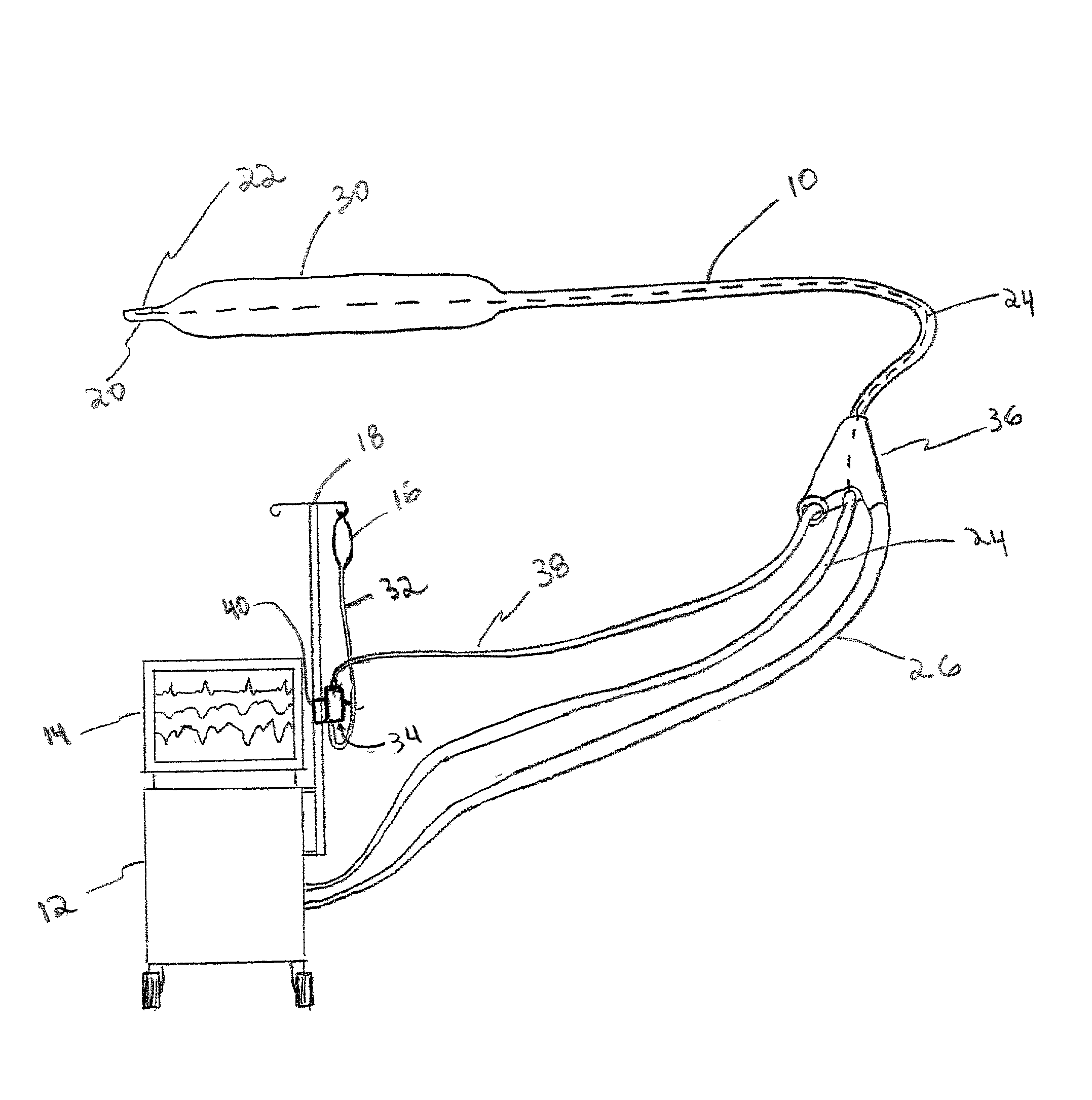
[0025] FIG. 1 illustrates the system of the present invention comprising an intra-aortic balloon ("IAB") catheter 10, an intraaortic balloon pump ("IABP") 12, a monitor 14, a drip bag 16, and a drip bag holder 18. FIG. 1 is a perspective view of the system with the IAB catheter 10 in the foreground and the IABP 12 is the background for clarity. The IAB catheter 10 contains a catheter pressure sensor 22 connected to its tip 20 and a Y-fitting 36 on its proximal end. The catheter pressure sensor 22 is connected to the IAB pump 12 via pressure sensing line 24, shown as ghost lines in the IAB catheter 10. Inflate / deflate tube 26, connecting an outer lumen of the IAB catheter 28 (see FIGS. 3-4) and the IABP 12, is used for inflation and deflation of a balloon membrane 30 connected between the tip 20 and a distal end of the IAB catheter 10. Drip tube 32 connects the pressurized drip bag 16 to a flush device 34. Saline tube 38 connects the flush device 34 with an inner lumen 60 of the IAB ...


PUM


Abstract

A balloon catheter having a micromanometer connected to the catheter and also a fluid-filled transducer system for adjusting micromanometer pressure measurements.

Description

BACKGROUND OF THE INVENTION[0001] 1. Field of the Invention[0002] The invention relates to a catheter having enhanced pressure sensing capabilities. More particularly, the invention relates to a balloon catheter having a micromanometer connected to the catheter and also a fluid-filled transducer system for adjusting micromanometer pressure measurements.[0003] 2. Description of the Prior Art[0004] A key function of many catheters is that of continuously monitoring blood pressure. In many cases, this monitoring must be performed with accurate measurement of high frequency components. For example, reliable detection of the dicrotic notch of the aortic blood pressure waveform typically requires a pressure signal having a bandwidth of 15 Hz or better. Detection of the dicrotic notch is generally used for the inflation / deflation timing of an intra-aortic balloon ("IAB") catheter.[0005] Conventional invasive pressure monitoring is performed with low-cost fluid-filled transducers. A typical...

Claims


Application Information

Patent Timeline
IPC IPC(8): A61B5/0215A61F2/958A61M25/00
CPCA61B5/0215A61M2025/0002A61M25/10A61M25/0032
Inventor SCHOCK, ROBERT B.WILLIAMS, JONATHANWALTERS, DANIEL A.
Owner DATASCOPE
Learn More