
Method and device for refining a glass melting

Inactive Publication Date: 2002-05-30
SCHOTT GLAS INNOVATION & TECH MANAGEMENT
View PDF2 Cites 17 Cited by
  • Summary
  • Abstract
  • Description
  • Claims
  • Application Information

AI Technical Summary

Benefits of technology

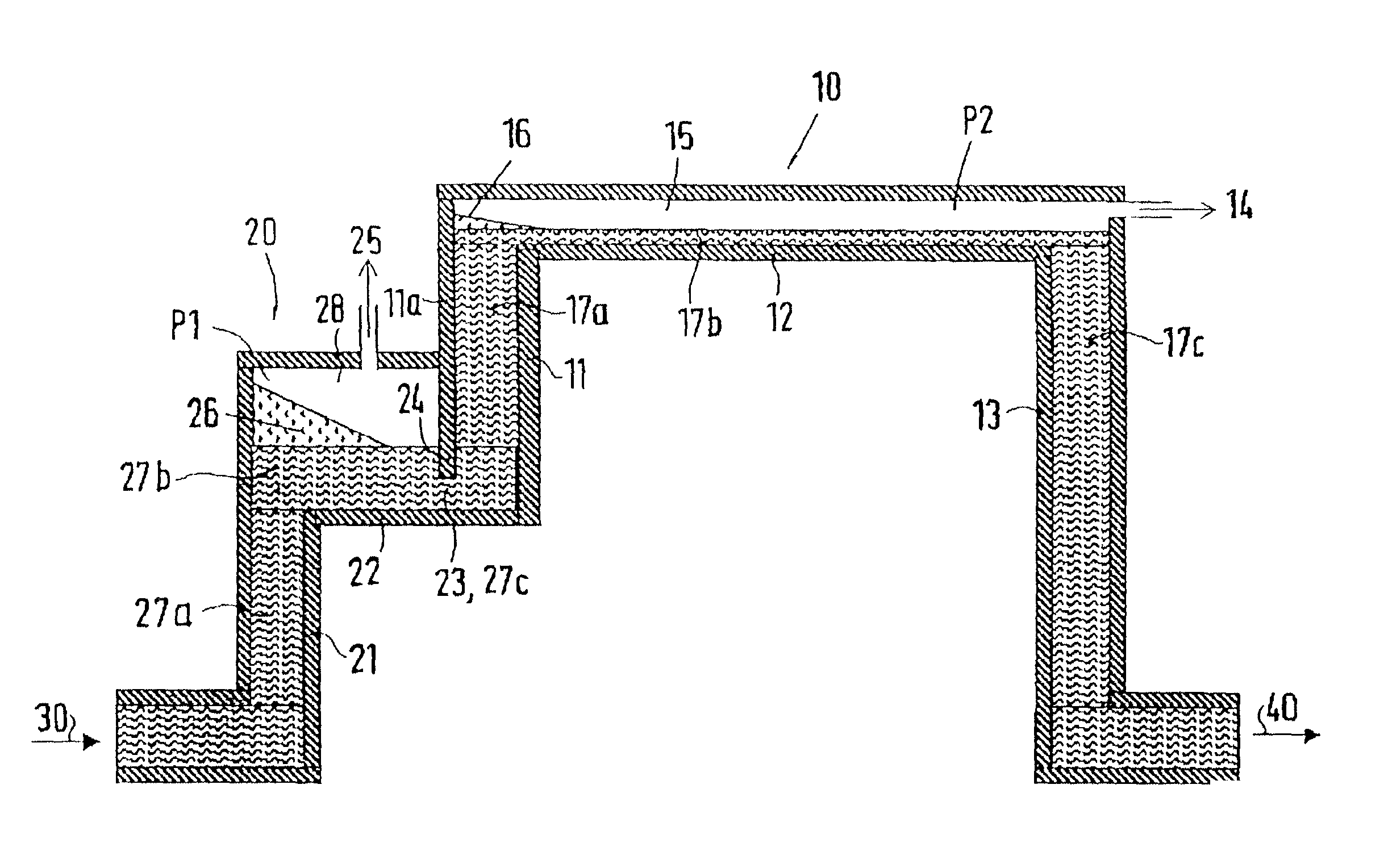
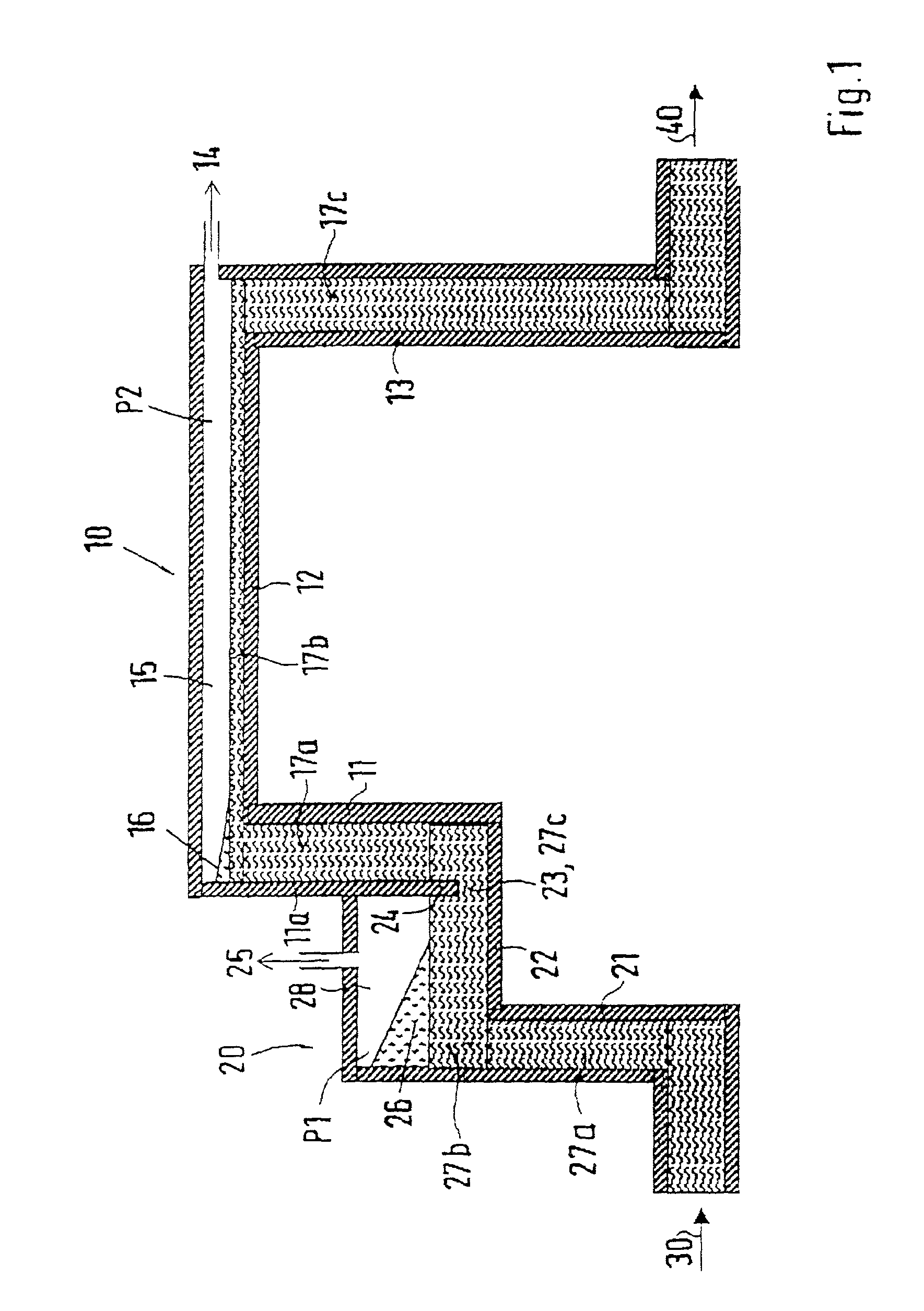
[0013] The step-by-step reduction of the pressure in the vacuum chambers results in an improved refinement, wherein in the first stage a reduction to a pressure down to approximately 100 mbar below the pressure, at which the first foam formation starts, is performed. Thus, the greatest foam volume is generated in the first stage. This pressure in the first stage lies in the range between 600 and 300 mbar. In the second and successive stages the pressure is selected so that the best refinement result is achieved.
[0014] The range, in particular of the end stage, is approximately between 300 and 30 mbar. The foam carried from the first stage is removed in the subsequent stages. Often two stages are sufficient for achieving a considerably more efficient solution, because in these stages the volume of foam generated is considerably smaller. Thus, the danger of foam or foam residue being entrained in the product is minimized or practically prevented.
[0016] An expanded portal-like underpressure apparatus, or several refining benches through which the glass flux successively flows, are used with this device. Thus it is possible to further reduce the entrainment of foam or foam residue in a simple manner in that the wall toward a subsequent vacuum chamber, which is in front in the direction of flow of the glass flux, of the intermediate ascending pipe partially extends into the glass flux of the previous refining bench.
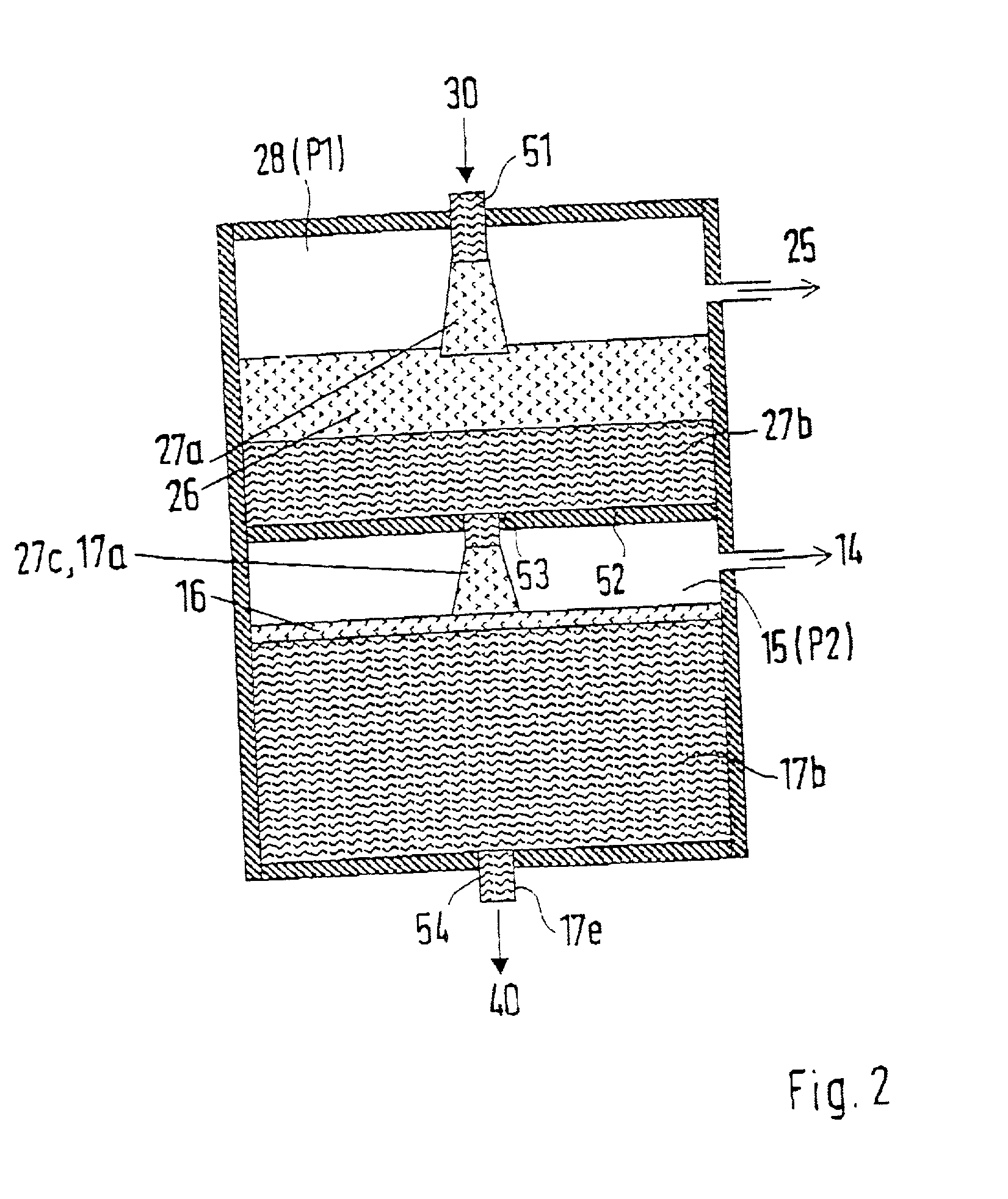
[0018] The container is formed as a multi-chamber container, wherein the glass flux flows sequentially through the vacuum chambers and is exposed to different pressures, so that the foam formation is also reduced from stage to stage and the refinement is improved. For generating the different pressures in the vacuum chambers the vacuum chambers have connecting openings for the vacuum pumps in the lateral walls of the multi-chamber housing.

Problems solved by technology

Therefore there is a considerable danger that foam or individual bubbles made of foam residue again enter into the product and result in losses in the yield or reduced quality of the product.
However, it has been shown that, depending on the glass composition, these additional steps do not always lead to a sufficient refinement of the glass melting.

Method used


Image

  • Method and device for refining a glass melting
  • Method and device for refining a glass melting
  • Method and device for refining a glass melting

Examples


Embodiment Construction

[0023] As shown in the sectional view in FIG. 1, the glass melting reaches the device for executing the method of this invention from an inlet basin 30. The glass flux 27a reaches a first horizontal refining bench 22 via a vertical inlet ascending pipe 21. The vacuum chamber 28 formed above the glass flux 27b of the refining bench 22 is at a pressure P1, which is generated by a vacuum pump 25. This pressure P1 lies approximately 100 mbar below the underpressure leading to foam generation in comparison to the atmospheric pressure and lies in the approximate range between 600 to 300 mbar. This results in a large foam volume 26, preferably above the inlet ascending pipe 21. The first refining bench 22 transitions into a vertical intermediate ascending pipe 11 of a second refining bench 12. In this case the wall 11a, which is in front in the flow direction, of the intermediate ascending pipe 11 partially projects into the glass flux 27b, which transitions into the intermediate ascending...


PUM

PropertyMeasurementUnit
Pressureaaaaaaaaaa
Pressureaaaaaaaaaa
Pressureaaaaaaaaaa

Abstract

A method and apparatus for refining a glass melting with a vacuum generated above a surface of a glass flux. Refinement is improved because the glass flux is conducted sequentially through several vacuum chambers, and the pressure in the successive vacuum chambers is reduced more and more relative the atmospheric pressure.

Description

[0001] 1. Field of the Invention[0002] This invention relates to a method for refining a glass melting with a vacuum generated above the surface of a glass flux. This invention also relates to a device for executing this method.[0003] 2. Description of Related Art[0004] Two different methods for refining a glass melting, which operate by a pressure above the glass flux which is reduced with respect to atmospheric pressure, are basically known.[0005] With the first method, the glass flux is introduced from above into a container in which a reduced pressure prevails. In the process, the glass is expanded because of the abrupt pressure change and a volume of foam is generated. With the disintegration of the foam, a glass melting is again generated later in the method, but with a clearly reduced content of gasses and dissolved bubbles in comparison to the glass melting supplied to the container. Such a method is disclosed in European Patent References EP 0 231 518 B1 and EP O 253 188 A1...

Claims


Application Information

Patent Timeline
IPC IPC(8): C03B5/225
CPCC03B5/2252
Inventor SCHMITT, STEFANKARETTA, FRANKEICHHOLZ, RAINER
Owner SCHOTT GLAS INNOVATION & TECH MANAGEMENT
Learn More