
Coolable nozzle and method for producing such a nozzle for a rocket engine

a technology of rocket engine and nozzle, which is applied in the field of coolable nozzle, can solve the problems of reducing the efficiency of rocket engine, reducing the cost of production, so as to improve the smoothness of the radially inwardly facing surface, improve the flow of hot gases, and improve the effect of smoothness

Inactive Publication Date: 2002-05-16
ASTRIUM GMBH
View PDF0 Cites 15 Cited by
  • Summary
  • Abstract
  • Description
  • Claims
  • Application Information

AI Technical Summary

Benefits of technology

[0011] to construct the nozzle body in such a way that it has a reduced weight compared to conventional nozzle bodies of this type and size while simultaneously having an improved strength, to withstand a high pressure of a cooling medium flowing through the nozzle body in operation;
[0035] Further load bearing layers outwardly applied to the outer ends of the nozzle body provide flanging areas in a simple and economical way for connection to the combustion chamber or to other components of the rocket engine.

Problems solved by technology

The welding operation leaves room for improvement because very long welding seams are required and damage to the tubular cross-sectional flow area may occur.

Method used


Image

  • Coolable nozzle and method for producing such a nozzle for a rocket engine
  • Coolable nozzle and method for producing such a nozzle for a rocket engine
  • Coolable nozzle and method for producing such a nozzle for a rocket engine

Examples


Embodiment Construction

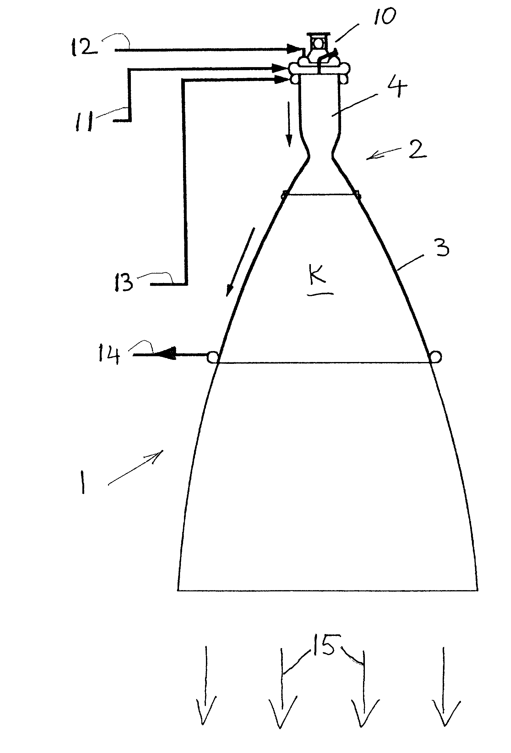
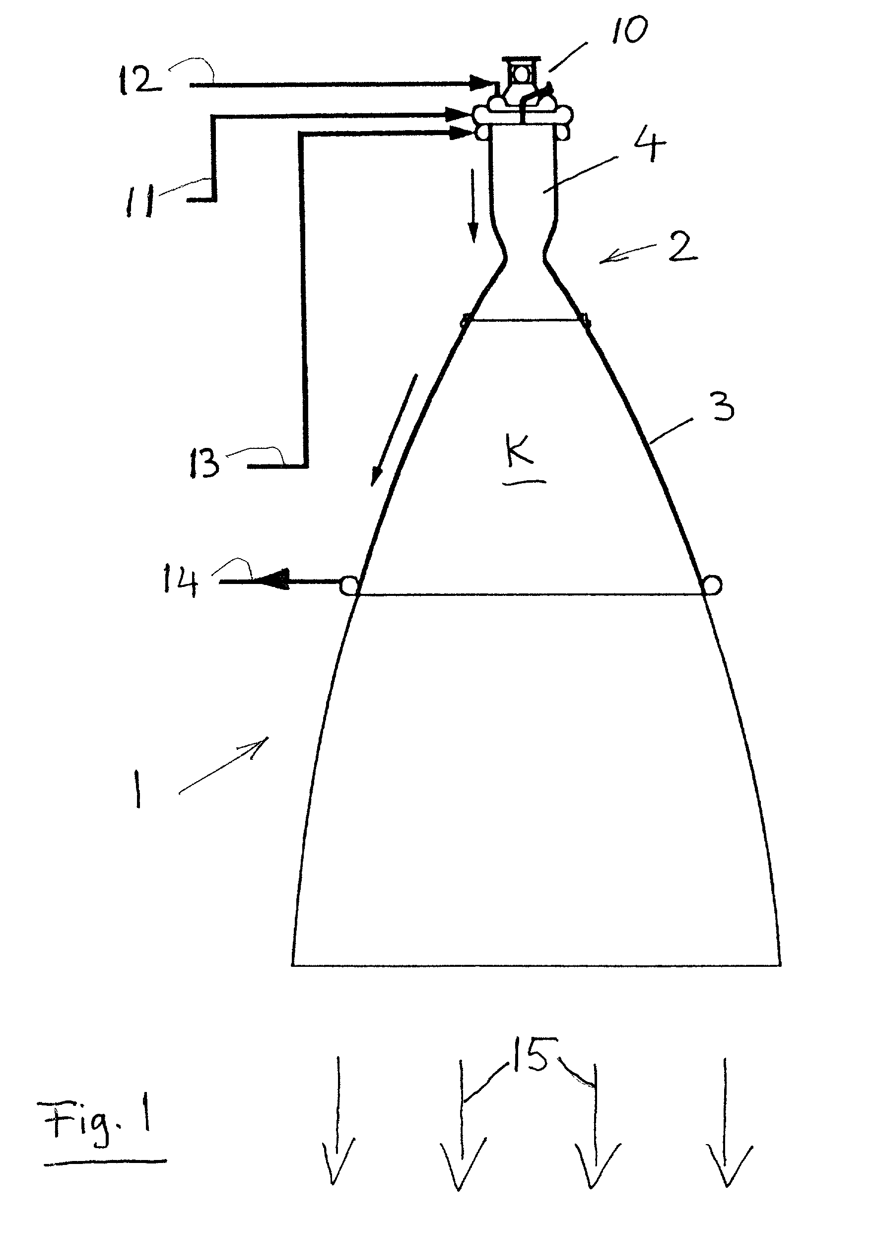
[0041] FIG. 1 shows schematically a rocket engine with a nozzle 2 according to the invention. The nozzle 2 includes a nozzle body 3 connected to one end of the nozzle 2 while the opposite nozzle end is connected to a combustion chamber 4. A fuel mixing system 10 is positioned for feeding mixed fuel into the combustion chamber 4. Fuel is supplied to the mixing system 10 by a fuel inlet 11 and an oxidant supply line 12. The fuel may, for example, be liquid hydrogen; the oxidant may, for example be liquid oxygen. Furthermore, a coolant inlet 13 and a coolant outlet 14 are provided. At least a portion K of the nozzle body 3 is regeneratively coolable by a coolant which is fed into an inlet 13 and let out through the coolant outlet 14. It is possible, for example, to use the liquid fuel provided for operating the rocket engine as a coolant. By way of a correspondingly powerful pump, not shown in FIG. 1, for generating a high pressure and a high flow rate. The liquid fuel is supplied to t...


PUM

PropertyMeasurementUnit
pressureaaaaaaaaaa
pressureaaaaaaaaaa
pressuresaaaaaaaaaa

Abstract

A regeneratively coolable nozzle for a rocket engine is formed by winding a tubular material (6) onto a winding mandrel to produce a helical composite structure (5), through which a coolant can flow during operation of the nozzle. The spiral composite structure (5) is fixed temporarily and the fixed composite structure (5) is removed from the winding mandrel. Then an inner heat resistant, load bearing layer (9) is applied to the radially inner hot-gas facing surface (H) of the fixed composite structure (5). The present nozzle is lightweight and withstands a high coolant pressure.

Description

PRIORITY CLAIM[0001] This application is based on and claims the priority under 35 U.S.C. .sctn.119 of German Patent Application 199 15 082.6 filed on Apr. 1, 1999, the entire disclosure of which is incorporated herein by reference.[0002] The invention relates to a nozzle and a method for producing nozzle for a rocket engine, whereby the nozzle is produced in such a way that it can be regeneratively cooled by means of a coolant flowing through tubular passages in the nozzle wall.[0003] Nozzles of rocket engines are parts which are subjected to extreme thermal loads calling for special measures to assure their stability during operation of the rocket engine. One option for such a measure involves regenerative cooling of the nozzle by means of a coolant which is conducted through the nozzle body under pressure. In the case of liquid propellant rockets a possible coolant is one of the fuel components. Thus for example in a rocket engine which uses hydrogen as a fuel, prior to supplying...

Claims


Application Information

Patent Timeline
Patent Type & Authority Applications(United States)
IPC IPC(8): B23P15/00C23C4/16C23C4/18F02K9/34F02K9/40F02K9/64F02K9/97
CPCB23P15/008F02K9/34F02K9/40Y10T29/49346F02K9/972F05D2250/15F05D2250/25F02K9/64
Inventor KRETSCHMER, JOACHIM
Owner ASTRIUM GMBH
Learn More