
Decoding system and method for digital communications

a decoding system and digital communication technology, applied in the field of digital communication systems, can solve the problems of not always practical to directly implement the algorithm in this way, restrict the type of decoding system that can be used, and corrupt the signal, so as to reduce the number of uncorrectable errors and packet loss

Inactive Publication Date: 2002-05-02
QUALCOMM INC
View PDF3 Cites 102 Cited by
  • Summary
  • Abstract
  • Description
  • Claims
  • Application Information

AI Technical Summary

Benefits of technology

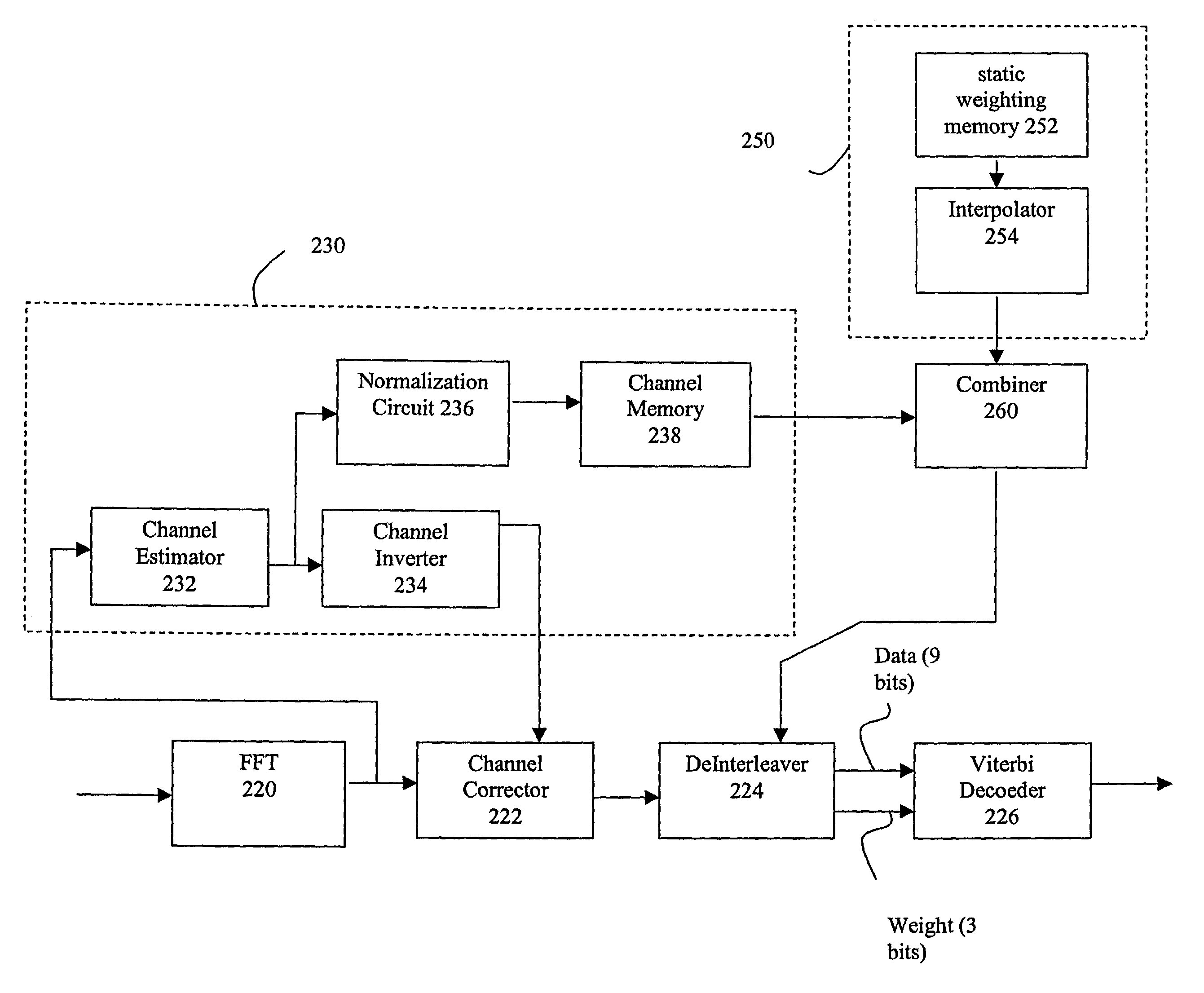
[0040] According to another aspect of the invention, these objects are achieved by providing a system which differentiates between data bits based on their estimated reliability, giving more emphasis to decoding reliable bits than unreliable bits using any of a variety of techniques. By differentiating between good and bad bits and de-emphasizing or ignoring unreliable bits, the system can provide a significant reduction in uncorrectable errors and packet loss.

Problems solved by technology

This is necessary because, as will be seen, the transmission process introduces a noise component into the transmitted signal which would corrupt the signal and render it useless were it impossible to be removed.
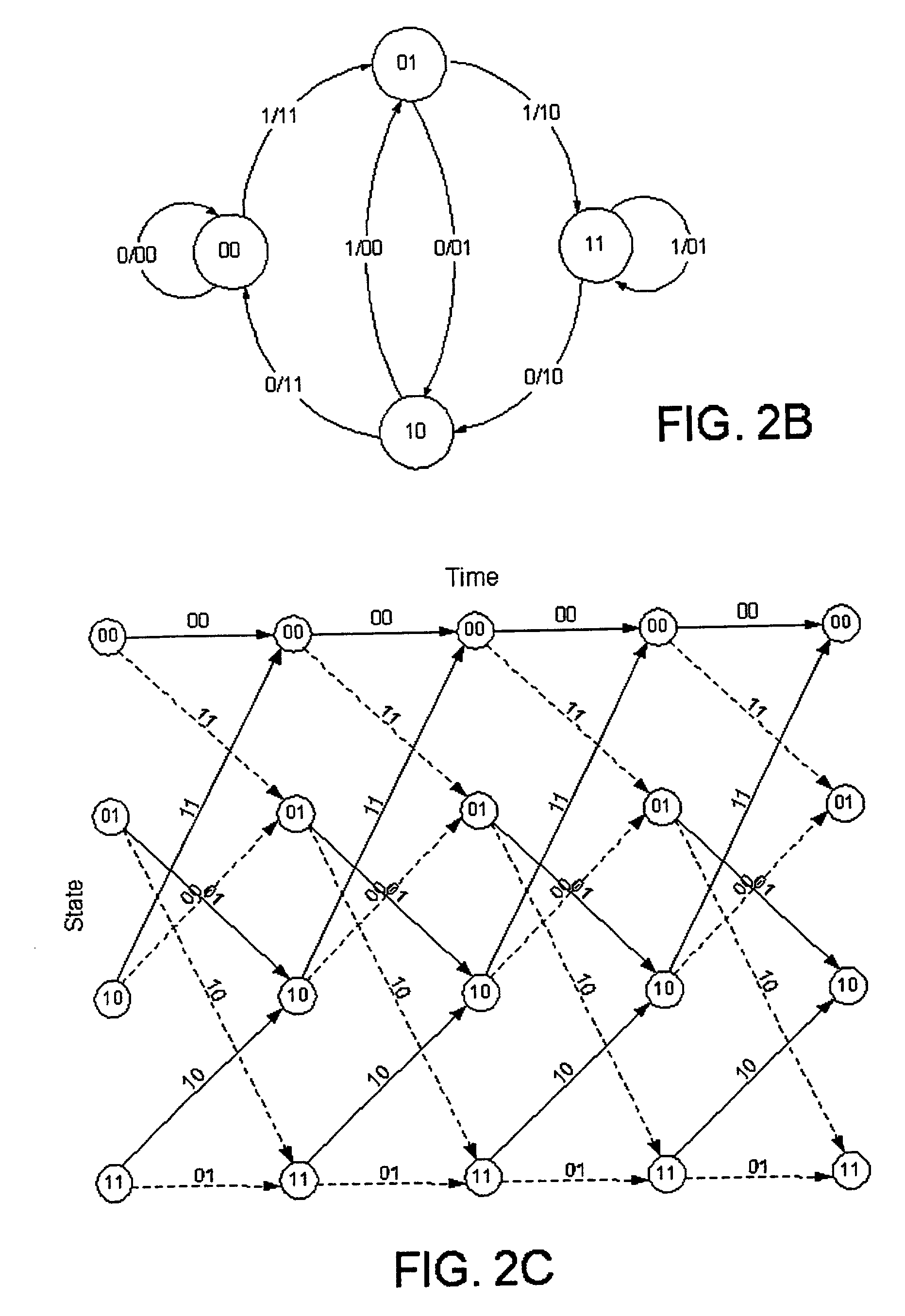
Although the Viterbi algorithm works well for situations such as those given above, it is not always practical to directly implement the algorithm in this way.
Additionally, some communication systems make use of interleaving and other techniques which restricts the type of decoding systems that can be used therein.
In this case, it is impossible to use Euclidean distance measurements to determine the proper weights to use in the algorithm, since the multiple bits represented by a single measurement are non-sequential in the trellis.
Further, the Viterbi algorithm in its current state does not allow for unequal weighting of bits based on knowledge of their error probability.
Also, one of the primary burdens for wireless data transceivers, in terms of both processing latency and consumed integrated circuit real estate, is data decoding such as described above.
Available wireless receivers fail to differentiate between reliable (good) and unreliable (bad) bits.
Within a multi-carrier environment, such a scheme further involves identifying which carriers have poor signal-to-noise ("SNR") characteristics and attendant high error rates, and puncturing / weighting bits in the identified carriers.

Method used


Image

  • Decoding system and method for digital communications
  • Decoding system and method for digital communications
  • Decoding system and method for digital communications

Examples


Embodiment Construction

[0060] The above arrangement described in the Background section works relatively well if the digital information is used to modulate the carrier signal directly; however, this is not always the case. For a variety of reasons, some communication systems employ alternative arrangements. For example, the IEEE 802.11 a communication standard uses a quadrature amplitude modulation (QAM) system in which the modulated carrier signal does not directly correspond to the information being transmitted, but to a position in a two-dimensional array or "constellation" of possible binary values. This constellation is known to the sender and receiver, so that a position transmitted to a receiving station can be accurately correlated with a corresponding digital sequence in the constellation.

[0061] Consider FIG. 5. This is a constellation which might be used in a 16QAM (16 bit quadrature amplitude modulation) coding system. Here, rather than providing a single digital output to the decoder 50, the ...


PUM


Abstract

A Viterbi decoding system interprets bits in received QAM constellations as many-valued parameters rather than binary valued parameters. It performs the Viterbi algorithm using these many-valued parameters to provide results superior to hard decision decoding. Rather than applying a hard 0-1 function to the QAM data, the system uses a non-stepped linear or curved transfer function to assign values to the bits. In another aspect, a system differentiates between data bits based on their estimated reliability, giving more emphasis to decoding reliable bits than unreliable bits using any of a variety of techniques. By differentiating between god and bad bits and de-emphasizing or ignoring unreliable bits, the system can provide a significant reduction in uncorrectable errors and packet loss.

Description

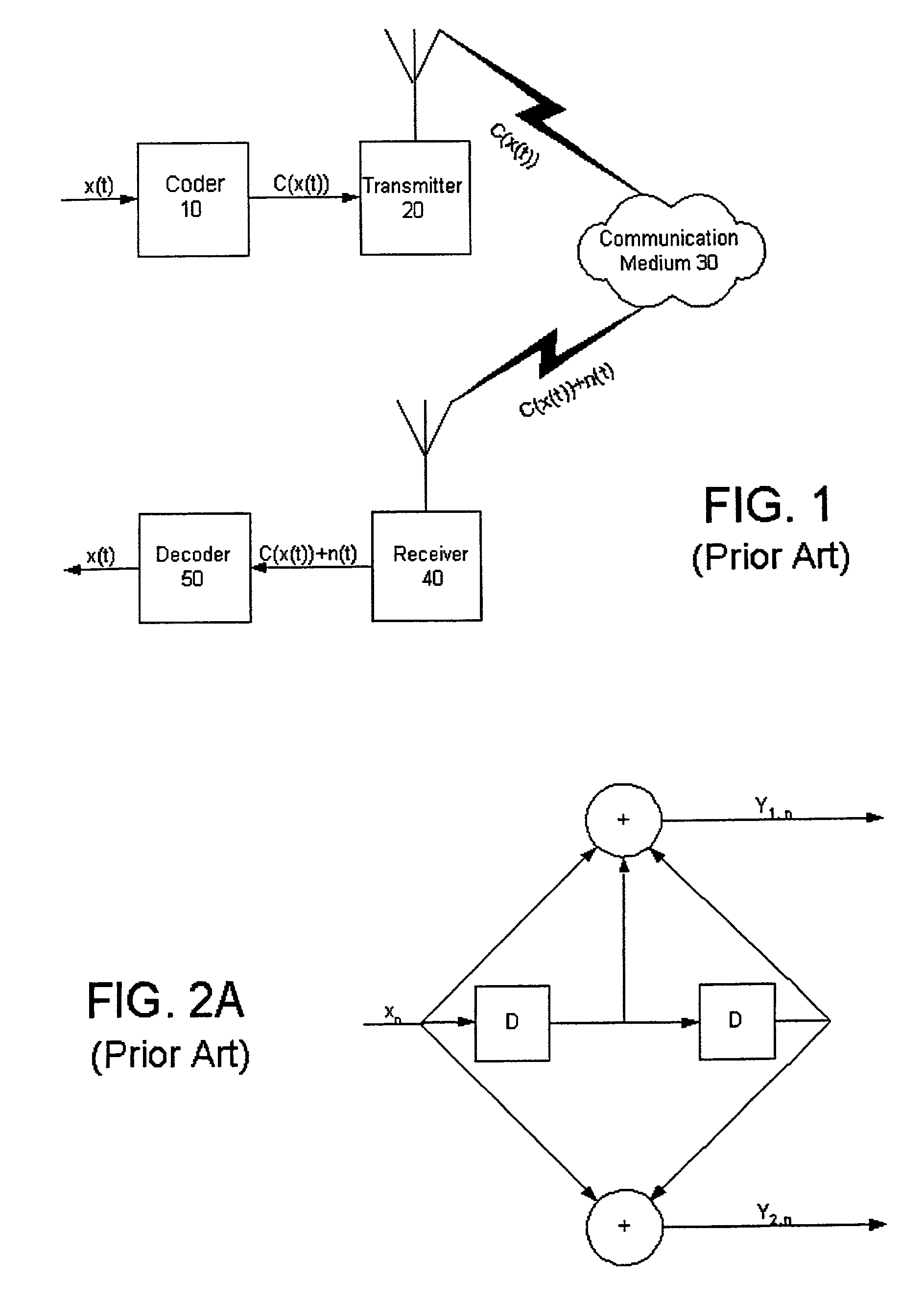
[0001] This is a continuation of part of U.S. application Ser. No. 09 / 535,902. Priority is claimed based on said application Ser. No. 09 / 535,902 and based also on Provisional Application No. 60 / 271,615 filed Feb. 26, 2001.[0002] 1. Field of the Invention[0003] The present invention relates to digital communication systems. More particularly, the invention relates to decision decoding of received digital information for use in subsequent decoding processes as well as to weighting selected received coded data based on its estimated reliability prior to decoding.[0004] 2. Background of the Related Art[0005] The process of transmitting digital information may in one sense be thought of as a four-step process as shown in FIG. 1. First, an incoming data stream of electrical digital signals x(t) is coded by a coder 10 to produce coded information C(x(t)) that is provided to a transmitter 20 which transmits the coded information C(x(t)) over a communication medium 30. The coder 10 processes...

Claims


Application Information

Patent Timeline
IPC IPC(8): H03M13/25H03M13/41H04J11/00H04L1/00H04L27/38
CPCH03M13/25H03M13/3961H03M13/41H03M13/6325H04L27/38H04K3/228H04L1/005H04L1/0054H04L25/067H03M13/6362H04L1/00
Inventor THOMAS, JOHN S.HUSTED, PAUL J.
Owner QUALCOMM INC
Learn More