
Graphical user interface for an enterprise intrusion detection system

Active Publication Date: 2007-11-06
FORCEPOINT FEDERAL
View PDF24 Cites 117 Cited by
  • Summary
  • Abstract
  • Description
  • Claims
  • Application Information

AI Technical Summary

Benefits of technology

[0009]The invention has several important technical advantages. Various embodiments of the invention may have none, some, or all of these advantages. One advantage of the present invention is that it provides a simplification of the data presented to an analyst, thereby improving the effectiveness of the intrusion detection system and related analysts. Further, the present invention may allow for more reliable detection of long-term attacks by the analyst. Another possible advantage of the invention comprises the ability to react to attacks in a more efficient manner. Other technical advantages of the present invention will be readily apparent to one skilled in the art.
is that it provides a simplification of the data presented to an analyst, thereby improving the effectiveness of the intrusion detection system and related analysts. Further, the present invention may allow for more reliable detection of long-term attacks by the analyst. Another possible advantage of the invention comprises the ability to react to attacks in a more efficient manner. Other technical advantages of the present invention will be readily apparent to one skilled in the art.

Problems solved by technology

Current enterprise intrusion detection systems (IDSs) often overwhelm analysts with data due to poor data aggregation, correlation, and presentation.
To overcome this shortcoming, an enterprise using a traditional IDS is faced with decisions that weaken the effectiveness of the IDS and / or are expensive to implement.
For example, the enterprise may limit the information collected by the IDS.
If the enterprise is unwilling to reduce the effectiveness of its conventional IDS, then the enterprise normally must hire additional expensive analysts to view the desired information that is overwhelming the current staff.

Method used


Image

  • Graphical user interface for an enterprise intrusion detection system
  • Graphical user interface for an enterprise intrusion detection system
  • Graphical user interface for an enterprise intrusion detection system

Examples


Embodiment Construction

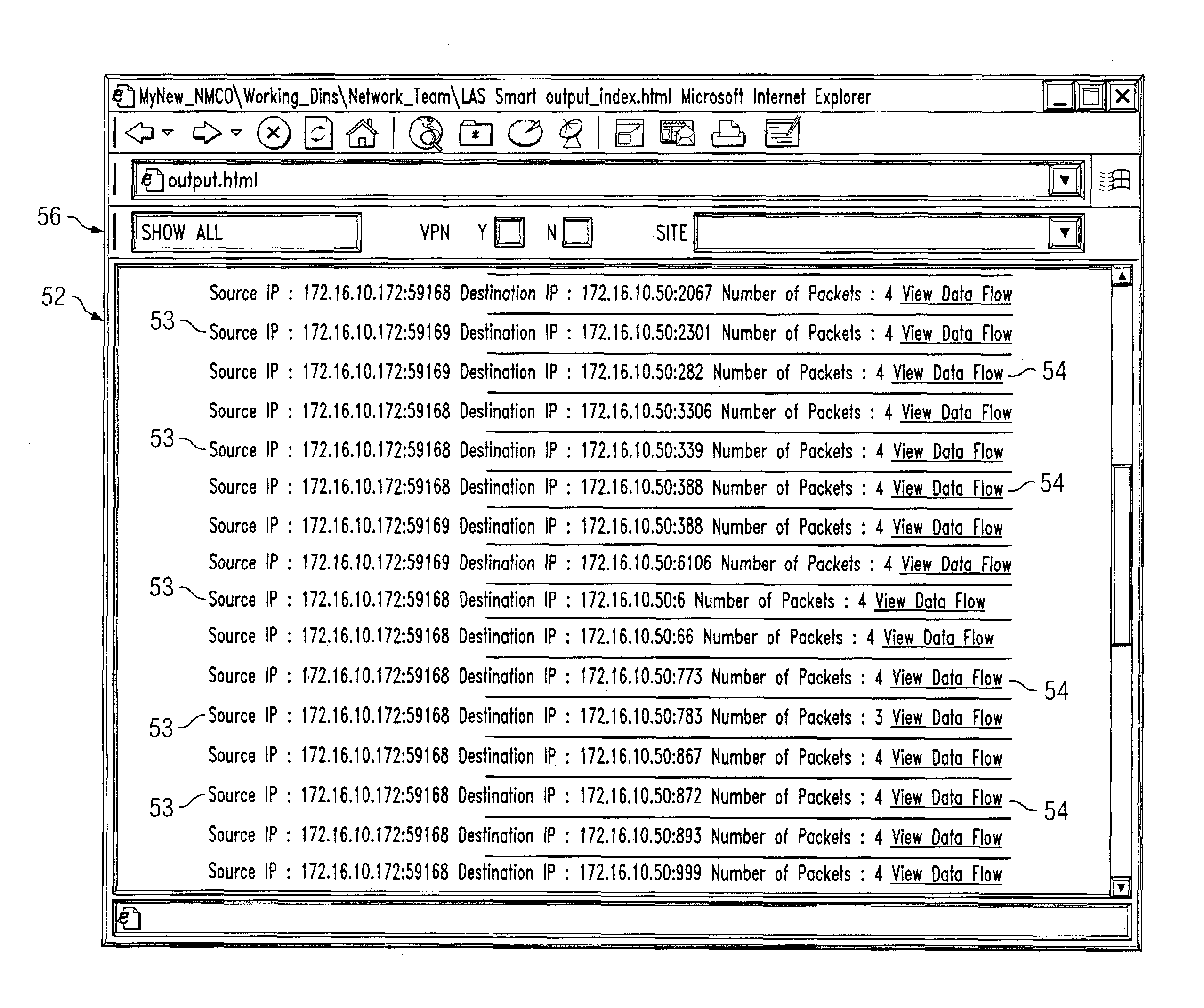
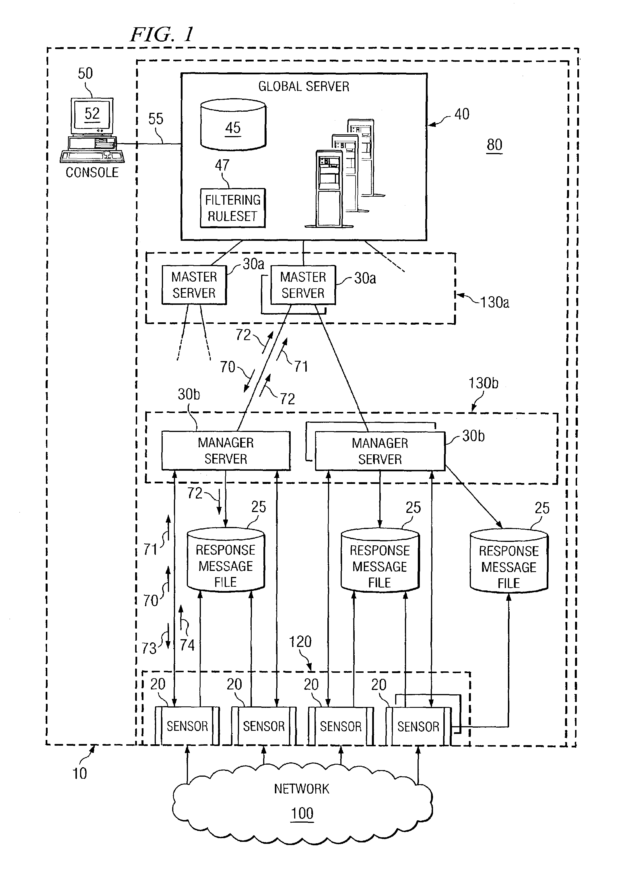
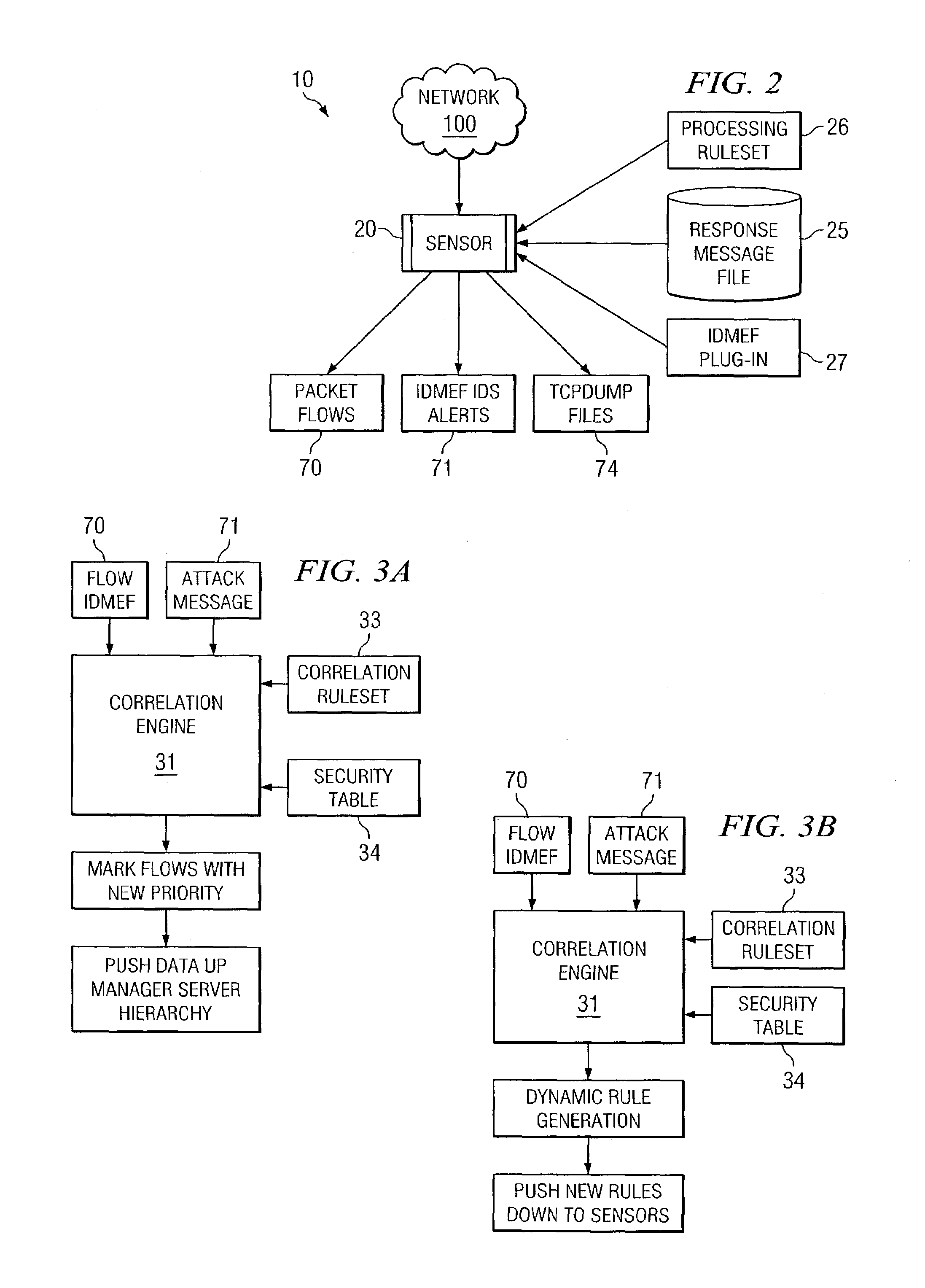
[0019]FIG. 1 illustrates a portion of a vertically extensible intrusion detection system 10 distributed across an enterprise system according to various embodiments of the present invention. The “enterprise” may comprise any business, government, organization, or other large entity that has multiple network channels or ports to an external network 100. For example, a business enterprise may include four ports for external network communications including email, internet, and dialup. In this example, intrusion detection system 10 monitors network communications on the three external ports and attempts to detect, locate, or block an attack on the business. An “attack” may be any malicious, destructive, or suspicious activity communicated from a source external to the portion of the enterprise protected by system 10. Attacks may include viruses, Trojan horses, worms, or any other piece of code or data that represents at least a portion of an unwanted attempt to access the protected por...


PUM


Abstract

A method for interfacing with a user of an enterprise intrusion detection system, the method comprises receiving at least one packet flow, each packet flow originating from a unique node in the intrusion detection system and comprising descriptive information and a plurality of packet headers. The descriptive information of a first subset of the received packet flows is communicated to a user based at least in part on a filtering ruleset. A second subset of the received packet flows is concealed from the user based at least in part on the filtering ruleset. In response to receiving a command from the user, the plurality of packet headers for at least one packet flow in the first subset is communicated to the user.

Description

RELATED APPLICATIONS[0001]This Application is related to:[0002]U.S. patent application Ser. No. 10 / 407,513 for a “VERTICALLY EXTENSIBLE INTRUSION DETECTION SYSTEM AND METHOD,” filed Apr. 4, 2003 by Jon-Michael C. Brook, Matthew C. Rixon, Randall S. Brooks, and Troy Dean Rockwood; and[0003]U.S. patent application Ser. No. 10 / 407,700 for a “DYNAMIC RULE GENERATION FOR AN ENTERPRISE INTRUSION DETECTION SYSTEM,” filed Apr. 4, 2003 by Jon-Michael C. Brook, Matthew C. Rixon, Randall S. Brooks, and Troy Dean Rockwood.TECHNICAL FIELD OF THE INVENTION[0004]This invention relates to intrusion detection systems and, more specifically, to a graphical user interface for an enterprise intrusion detection system.BACKGROUND OF THE INVENTION[0005]Intrusion detection systems are used by an enterprise to detect and identify unauthorized or unwanted use (commonly called an attack) of the enterprise's computer network, which normally comprises a large number of nodes and network operations centers (NOCs...

Claims


Application Information

Patent Timeline
IPC IPC(8): G06F3/00G06F11/30
CPCH04L63/1416G06F21/552
Inventor BROOK, JON-MICHAEL C.RIXON, MATTHEW C.BROOKS, RANDALL S.ROCKWOOD, TROY DEAN
Owner FORCEPOINT FEDERAL
Learn More