Light guide plate, surface light source device and liquid crystal display

a surface light source and light guide technology, applied in the direction of optical light guides, instruments, optics, etc., can solve the problems of reducing light energy efficiency, hardly providing uniform and effective emission, and delivering unsatisfactory brightness, so as to achieve easy control and heightened applicability to front-lighting arrangements

Inactive Publication Date: 2002-04-11
ENPLAS CORP
View PDF7 Cites 20 Cited by
  • Summary
  • Abstract
  • Description
  • Claims
  • Application Information

AI Technical Summary

Benefits of technology

0035] The present invention aims to overcome the above-mentioned problem s of prior arts. That is, an object of the present invention is to improve an light guide plate used for emitting light, which is introduced from a side end face (incidence end face), from an emission face so as to have no region which light is hard to reach and to have an emission direction easily controllable and further to have a heightened applicability to a front-lighting arrangement.

Problems solved by technology

As known well, a simply transparent light guide plate to which no modification is applied is capable of deflecting light slightly, providing an unsatisfactory brightness.
Although employment of a light diffusion sheet brings some increase in frontal emission, it involves a wide light diffusion which leads to reduction in light energy efficiency.
Ways based on (2) or (3) hardly provide uniform and effective emission.
Accordingly, it is hardly expected to realize a highly efficient emission.
In particular, it is not advantageous that they fail to generate light which travels from the back face to the emission face.
However, in practice, prior arts fail to control propagating direction of emission sufficiently.
1. There is a region which is located behind the slope 5b as viewed from the incidence end face 2 and is hardly supplied with light. Therefore, a reduced formation pitch d gives no increasing in direction conversion efficiency, with the result that the emission face 3 is apt to show an unevenness in brightness.
2. Direction control regarding in a plane parallel to the incidence end face is not sufficiently effected. For example, if travelling directions of G1, G2 shown in FIG. 1a are parallel to the emission face 3 but not perpendicular to the incidence end face 2, emitted light G1', G2' will diverge to the right and left as viewed from the incidence end face 2. There is a remarkable amount of light component which is not perpendicular to the incidence end face 2 in an actual light guide plate. Therefore, it is difficult to obtain an emission which is directed to a desirable spatial direction (regarding in both planes perpendicular and parallel to the incidence end face).
3. Leaking of light from the back face 4 occurs easily because direction conversion to produce light directed to the emission face 3 relies on a single reflection (slope 5a). In other words, a condition of total reflection is broken easily at the reflection for direction conversion. For example, if beams G1', G2' are to be directed toward a generally frontal direction, inner incidence angle is about 45 degrees. This value is roughly equal to the critical angle of an interface between acrylic resin, which is a typical material of a light guide plate, and air. Therefore, a remarkable part of light directed somewhat downward leaks through the slope 5a.
However, the above-improved light guide plate or surface light source device employing it remains a problem unsolved and required to be overcome.
This problem is that they bring display contrast and resolving characteristics which are somewhat unsatisfactory if applied to a liquid crystal display of front-lighting type.

Method used


Image

  • Light guide plate, surface light source device and liquid crystal display
  • Light guide plate, surface light source device and liquid crystal display
  • Light guide plate, surface light source device and liquid crystal display

Examples


first embodiment

[0063] (1) First Embodiment

[0064] FIGS. 4a and 4b illustrate an outline of the first embodiment in accordance with the present invention. FIG. 4a is a plan view from the back face side of a light guide plate and FIG. 4b is a side view from the left side in FIG. 4a.

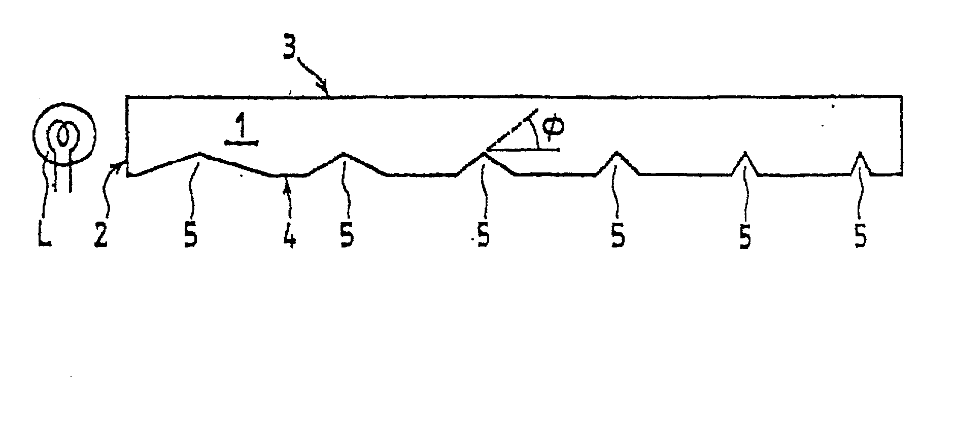
[0065] Referring to FIGS. 4a and 4b, a light guide plate 10 made of a transparent material such as acrylic resin, polycarbonate (PC) or cycloolefin-type resin has a minor face (side end face) to provide an incidence end face 12. A rod-like primary light source (cold cathode tube) L1 is disposed along the incidence end face 12 which is supplied with light from the light source. One of major faces 13, 14 of the light guide plate 10 provides an emission face 13. The other major face (back face) 14 is provided with a great number of micro-reflectors 20.

[0066] A well-known liquid crystal display panel PL is disposed on the outside of the emission face 13, providing a backlight-type liquid crystal display. Note that indicated di...

second embodiment

[0107] (2) Second Embodiment

[0108] Although the second embodiment has an outline similar to that of the first embodiment as shown in FIGS. 4a, 4b, the second embodiment employs another light guide plate different from one employed in the first embodiment. In the second embodiment, a light guide plate 30 as shown in FIG. 8 is adopted instead of the light guide plate 10.

[0109] The light guide plate 30 is made of a transparent material such as acrylic resin, polycarbonate (PC) or cycloolefin-type resin, which has a side end face to provide an incidence end face 32.

[0110] A rod-like primary light source (cold cathode tube) L2 is disposed along the incidence end face 32 which is supplied with light from the light source. It is noted that the cold cathode tube L2 has a light emitting portion length of which is smaller a little than that of the incidence end face 32. Both ends provide electrode portions EL1 and EL2 which are not capable of emitting light. Such a design is often employed in...

third embodiment

[0118] (3) Third Embodiment

[0119] Although the third embodiment has an outline similar to that of the first or second embodiment, the third embodiment employs another light guide plate different from ones employed in the first and second embodiments. In the present embodiment, a light guide plate 40 as shown in FIG. 9 is adopted. The light guide plate 40 is made of a transparent material such as acrylic resin, polycarbonate (PC) or cycloolefin-type resin, having two side end faces to provide two incidence end faces 42a, 42b.

[0120] Rod-like primary light sources (cold cathode tube) L3, L4 are disposed along the incidence end faces 42a, 42b which are supplied with light from the light sources, respectively. A great number of micro-reflectors 20 are formed on a back face 44. Arrangement and orientation of the micro-reflectors 20 involves the following features.

[0121] 1. Covering rate and orientation of the micro-reflectors 20 are designed as follows.

[0122] First, covering rate and orie...


PUM

PropertyMeasurementUnit
inner incidence angleaaaaaaaaaa
distanceaaaaaaaaaa
sizeaaaaaaaaaa

Abstract

A light guide plate, surface light source device and liquid crystal display of a double-reflection-direction-conversion type have a heightened applicability to an front-lighting arrangement. A back face 14 of a light guide plate 10 is provided with micro-reflectors shaped like trapezoids each of which has a bottom face extending generally in parallel with a general plane of the back face 14. A main input light H10 to a micro-reflector 20 is incident to an incidence end face 12 (at point a) and inputted thereto in a somewhat downward inclined direction. An inner input light is inner-reflected mainly by slopes 21 and 22 successively (at points b and c), becoming an inner output light IO directed to an emission face 13. The inner output light IO is emitted from the emission face 13 (at point d), being supplied to an LCD panel or the like after transmitting through a light diffusion sheet DF (points e and f). An application to a front-lighting arrangement prevents the displayed image from being blurred since a returning light coming from an LCD panel is hardly bent by the micro-reflectors.

Description

[0001] 1. Field of Invention[0002] The present invention relates to a light guide plate which is supplied with light sideways and deflects the light to output from an emission face, further relating to a surface light source device employing the light guide plate, still further relating to a liquid crystal display employing the surface light source device for lighting of LCD panel, in particular, front-lighting of it.[0003] 2. Related Art[0004] A surface light source device of a type comprises a light guide plate having an end face, through which light is introduced, and two major faces (i.e. faces larger than end faces) one of which provides an emission face, being employed for various uses such as back-lighting or front-lighting for a liquid crystal display. Basic performance of surface light source devices of such a type greatly depends on light guide plates employed therein.[0005] A basic function of a light guide plate is to change a propagation direction (roughly in parallel w...

Claims


Application Information

Patent Timeline
Patent Type & Authority Applications(United States)
IPC IPC(8): F21V8/00G02B6/00G02F1/1335G02F1/13357
CPCG02B6/0036
Inventor OHKAWA, SHINGO
Owner ENPLAS CORP
Why Eureka
Try Eureka