Plastic profile for sealing air gaps between body parts of motor vehicles

a technology for air gaps and motor vehicles, applied in the field of foam strips, can solve the problems of difficult and complicated fixing or inserting of foam strips into gaps to be sealed, deformation of enamel spots, etc., and achieves the effects of safe and durable support of foam profiles, convenient removal from car body parts, and efficient adhesion

Inactive Publication Date: 2002-02-21
VOSS KLAUS WILHELM
View PDF0 Cites 8 Cited by
  • Summary
  • Abstract
  • Description
  • Claims
  • Application Information

AI Technical Summary

Benefits of technology

[0013] This has the advantage that the adhesive surface on the gap inner side can be configured with any variable size and that it is not exposed to any bending load. This prevents a shearing off, and the adhesive joint has a high durableness or is stable at least for the duration of the application.
[0101] The guiding rail is placed on the base plate movable thereto so as to be able, when moving the applicator along a gap to be sealed, to avoid any obstacles without having to set down the applicator.

Problems solved by technology

Such soil particles can precipitate on the fresh distributed enamel and lead to a defective enamel spot.
Nevertheless, a drawback of the known foam strips for sealing and masking is to be found in the fact that the application possibilities of a specific foam strip are limited to a certain problem task, since the foam strip can only be used for a defined joint width or the like because of the dimensioning and the plastic moulding of the specific foam strip.
Furthermore, the fixing or the inserting of the strips into a gap to be sealed is difficult and complicated, since the foam strip has to be much bigger than the gap to be sealed for a firm support of the foam strip.
However, this oversize must first be pressed through the gap which is much narrower.
In unfavourable cases, it comes to a peeling off of the adhesive joint so that, already after a short time, the foam strip works loose from the car body part and does not guarantee an effective sealing of the gap any longer.
When positioning such strips or combinations of foam strips with paper adhesive strips, the sticking work often has to be performed under very confined conditions in which the hollow spaces are so narrow that a perfect sticking can only be obtained with a correspondingly designed applicator.
Especially at places of difficult access, there are special difficulties, because of this lack of space, since it comes again and again to unintended contacts between the foam strip or between the foam strip lined with adhesive paper and surfaces of the spots to be sealed, for example of a car body.
When fitting plastic profiles for gap sealing which are joined with glue or with a paper adhesive strip to a surface of a gap inner side, it has thus proved to be a problem that these plastic profiles are difficult to handle with, since, when positioning the sealing profile in a gap to be sealed, the adhesive layer comes into contact prematurely, i.e. before the sealing profile is in the desired final position, with a surface and adheres thereto.
This makes difficult or, in the unfavourable cases, prevents an exact positioning of the plastic profile in a gap to be sealed.

Method used


Image

  • Plastic profile for sealing air gaps between body parts of motor vehicles
  • Plastic profile for sealing air gaps between body parts of motor vehicles
  • Plastic profile for sealing air gaps between body parts of motor vehicles

Examples


second embodiment

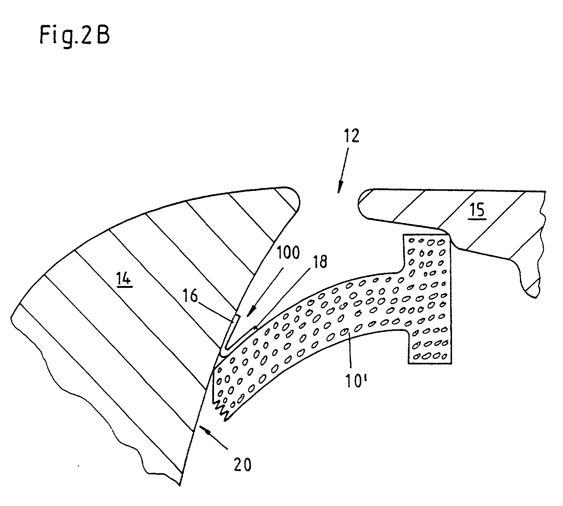
[0188] FIGS. 3A and 3B illustrate the same process as FIGS. 2a and 2B, however with another embodiment of the foam strip 10. For this embodiment, the foam strip 10' is approximately rectangular. A represented second embodiment of the applicator 400 is appropriately adapted with its rail 78 of the receptacle 72. As may be seen in FIG. 3B, the hinge type swinging open of the fixing means again assures that the adhesive joint between the leg 16 and the car body part 14 is, as far as possible, free from the lateral power on the foam strip 10'.

[0189] Moreover, the applicator 400 has a second stopper 84, adjustable over a screw 88, and an elastic rubber profile 76 at the lower end in FIG. 3A of the first stopper 82. This rubber profile 76 secures the foam strip 10' in the applicator 400, since a corresponding design of the rail 78 and of the foam strip 10, like in FIG. 2A, is missing. Moreover, the rubber profile 76 supports the realization of the adhesive joint between the leg 16 and the...

embodiment 200

[0191] FIGS. 6 and 7 show a further preferred embodiment 200 of the fixing means according to the invention. This fixing means is carried out in two layers, namely with a first layer 50 and a second layer 52. The first layer 50 is a solid nondetachable glue 56 between the second layer 52 and the foam strip 10 or 10'. The first layer 50 constitutes an adhesive joint between the foam strip 10 or 10' and the second layer 52 which is greater than the respective inherent strength of these layers and assures in this way a solid bonding between the fixing means 200 and the foam strip 10 or 10'.

[0192] The second layer 52 is preferably a paper or a plastic strip and is sufficiently big dimensioned for a desired adhesive force.

[0193] The FIGS. 6 and 7 or 4 and 5 only differ from each other by different embodiments of the profile of the plastic strip 10 or 10'. Once a rectangular profile is represented, once a T-shaped profile; however, any other profile, adequate for sealing the gap 12, is al...

embodiment 1200

[0209] The embodiment 1200 according to FIG. 15 is particularly preferred, since here the fixing means additionaly has a protective function against enamel and its solvents through the sunk joint 220. This is due to the fact that, after the fixing means has adhered to a surface, the lateral borders 222 additionally seal the area of the surface around the adhesive side outwards and thus avoid the penetration of distributed enamel or its solvents. This is represented in FIGS. 31 and 32 for a better illustration.


PUM

PropertyMeasurementUnit
Angleaaaaaaaaaa
Angleaaaaaaaaaa
Lengthaaaaaaaaaa

Abstract

For sealing the gap, especially the air gap between two body parts (14, 15) of motor vehicles, a plastic profile in the form of a foam strip (10') with a fixing means (100) is proposed which has at least two legs (16, 18) which are hinged together, whereby a first leg (16) is joined to the foam strip (10') by means of a first adhesive layer and a second leg (18) is provided with a second adhesive layer for joining to a gap inner side (20). (FIG. 2B)

Description

SCOPE[0001] The invention relates to a plastic profile in the form of a foam strip for sealing a gap, especially for sealing the air gap between body parts of motor vehicles, whereby the surface of the foam strip is partially provided with an adhesive layer, as well as to an applicator to bring in a foam profile, especially a rectangular, a L-shaped or a T-shaped foam profile which is provided with an adhesive layer at least on one side, into a gap to be sealed or into a joint to be sealed, especially into a gap or a joint between a fixed body part and a movable body part of a vehicle.STATE OF THE ART[0002] Numerous embodiments of foam strips are known for being used as sealing and / or masking strips, for example for the partial enamelling of motor vehicles or the like. In this respect, not only the penetration of colour mist into a gap of car body parts should be avoided. On the contrary, it should also be avoided that soil particles are ejected out from the joints by air whirling w...

Claims


Application Information

Patent Timeline
IPC IPC(8): B05B12/24B05B12/26B05B15/04B60J10/00B60R13/02B60R13/06F16J15/02F16J15/06F16J15/32
CPCB05B15/0456B05B15/0462B05B15/0468B60J10/0014B60J10/0071B60J10/0088Y10T428/29B60R13/06F16J15/022F16J15/024F16J15/061F16J15/3208B60R13/02B60J10/20B60J10/34B60J10/45B05B12/24B05B12/26B05B12/265Y10T428/249982Y10T428/249984
Inventor VOSS, KLAUS-WILHELM
Owner VOSS KLAUS WILHELM
Why Eureka
Try Eureka