Wave shaping sound chamber

a sound chamber and wave shaping technology, applied in the field of audio loudspeaker systems, can solve the problems of low efficiency of arrays of direct radiators, multiple source arrays, and inability to construct arrays of such devices, and achieve the effect of zero acoustic interference and suitable flatness

Inactive Publication Date: 2002-02-07
ADAMSON ALAN BROCK
View PDF0 Cites 42 Cited by
  • Summary
  • Abstract
  • Description
  • Claims
  • Application Information

AI Technical Summary

Benefits of technology

[0026] The primary means of controlling the path lengths through the sound chamber is to increase the thickness of the inner body and to correspondingly increase the outer shell so that the portion of the sound wave that encounters this sectional shape must travel further than that portion of the sound wave that encounters a thinner shaped section of the inner body.
[0029] Since the curvature of the wavefront in the horn throat is independent of the degree of path length difference across the width of the sound chamber, any amount of curvature is achievable. For example, the path lengths through the sound chamber could be increased at the ends of the aperture and made shorter in the middle with the result that the curvature of the wavefront would be increased.
[0037] It is a further object of the present invention to provide a method that allows more than one transducer operating in the same frequency range to produce a common wavefront with virtually zero acoustical interference.

Problems solved by technology

The dimensional limit dictates that an array of such devices cannot be constructed so that the horn throats are in close proximity to one another; the throats are displaced by the size of the attached driver.
The result of any multi-element combination is that of an array that generates multiple spherical sound waves with significant interference effects.
The problems of the resulting multiple source array are well documented in the literature.
None of the improvements of individual horns has resulted in an array of horns that eliminates the interference effects found in multi-source arrays.
Such arrays of direct radiators are low in efficiency and the method does not work for typical horn loaded high frequency drivers because the wavelengths at the highest audio frequencies are generally a factor of ten shorter than the dimensions of the drivers used thus preventing mutual coupling.
Furthermore, the use of small direct radiators severely restricts the operating bandwidth.
Any wavefront other than a cylindrical wave of the correct radius will propagate down the waveguide through reflection and higher order modes that are quite undesirable according to Geddes.
However, in the axial plane orthonormal to the first plane considered, the expansion of the sound chamber is large.
A very important limitation of the Adamson and the Heil devices is that there is significant required boundary divergence in order to achieve the required length at the exit aperture.
As the wave nears the exit, the diverging upper and lower walls of these sound chambers cause significant reflections.
This results in an obvious and measurable deterioration in the summation of the wavefronts of adjacent sound chambers, particularly at the highest frequencies.

Method used


Image

  • Wave shaping sound chamber
  • Wave shaping sound chamber
  • Wave shaping sound chamber

Examples


Embodiment Construction

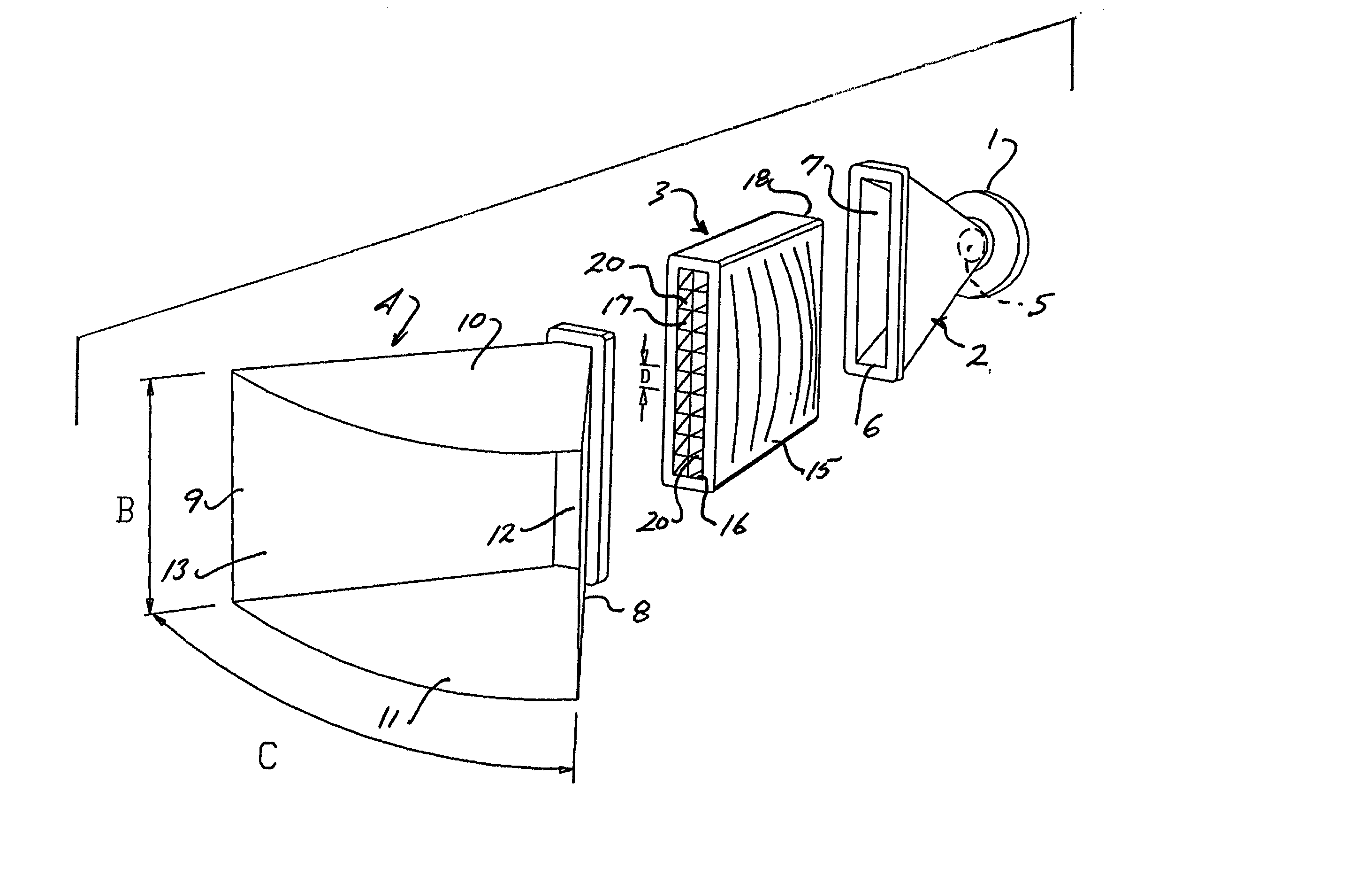
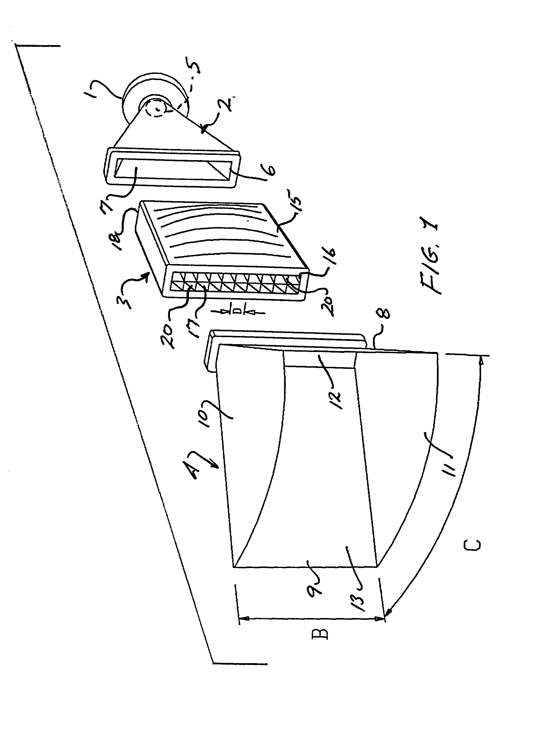
[0063] With reference to FIG. 1., the present invention includes an acoustic transducer 1, a primary waveguide shown in the form of a simple horn 2, a wave shaping sound chamber 3 and a secondary waveguide 4. The primary waveguide 2 comprises an inlet aperture 5 and an outlet aperture 6 that are connected by an expanding wedge shaped acoustic conduit 7.

[0064] The secondary waveguide 4 comprises sidewalls 8 and 9, and upper and lower walls 10 and 11 that define the desired properties of the sound wave that will be transmitted by the waveguide. The secondary waveguide also includes an inlet aperture 12 and an outlet aperture or mouth 13.

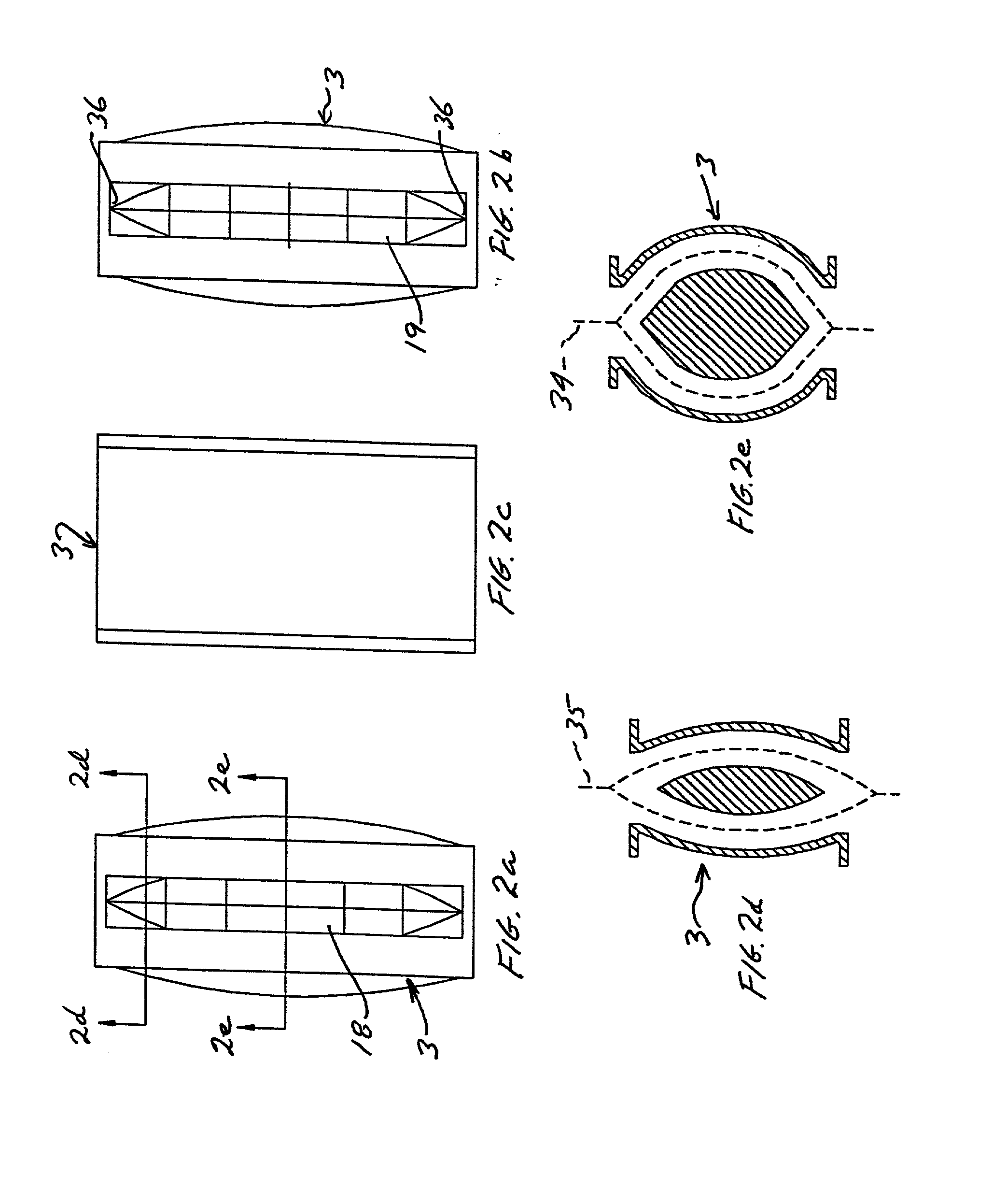
[0065] The wave shaping sound chamber 3 comprises an outer shell 15 and an inner body 16 forming a conduit 17 for the transmission and shaping of a sound wave and also includes an inlet aperture 18 and an outlet aperture 19. For best performance vanes 20 are placed within the sound chamber spaced at a distance "D" with respect to one another and which ...


PUM


Abstract

A loudspeaker system containing wave-shaping sound chambers with approximately rectangular inlets and outlets of substantially the same size that are used to flatten or control the curvature of the acoustic wavefronts contained within system waveguides. Control of the degree of curvature of the wavefront enables the development of a wide variety of multi-waveguide arrays. The sound chambers are placed between a waveguides and a flattened conical horns of secondary waveguides. The sound chambers transform the curvature of the typical fan shaped wavefront that results from a conical horn throat into a wavefront that approximates a planar or curved rectangular ribbon of sound.

Description

BACKGROUND OF THE INVENTION AND PRIOR ART[0001] 1. Field of the Invention[0002] This invention is generally directed to audio loudspeaker systems and more particularly to such systems, which incorporate sound chambers which transform fan shaped wavefronts issuing from primary waveguides into rectangular planar or curved wavefronts which are directed to sound disseminating secondary waveguides.[0003] 2. Description of the Related Art[0004] Large sound systems contain multiple transducers operating in the same frequency band in order to achieve the required sound pressure level (SPL) and the required acoustical coverage of its intended target. The highest efficiency sound systems use the principle of horn loading to achieve maximum SPL. The horn and its associated driver have two particular characteristics of interest: the driver is by definition larger than the throat of the horn; and wavefronts are radiated in a generally spherical shape. The dimensional limit dictates that an array...

Claims


Application Information

Patent Timeline
IPC IPC(8): G10K11/22H04R1/28
CPCG10K11/22G10K11/26H04R1/30H04R1/345H04R1/403H04R2201/34H04R2400/13
Inventor ADAMSON, ALAN BROCK
Owner ADAMSON ALAN BROCK
Why Eureka
Try Eureka