Component source interchange gantry

a technology of component source and gantry, which is applied in the direction of article separation, packaging, thin material processing, etc., can solve the problems of additional operation cost and not only labor

Inactive Publication Date: 2002-01-10
DELAWARE CAPITAL FORMATION
View PDF0 Cites 12 Cited by
  • Summary
  • Abstract
  • Description
  • Claims
  • Application Information

AI Technical Summary

Benefits of technology

[0007] The present invention is a component source interchange gantry designed to automatically store and replenish semiconductor components stored on both wafers used in a direct die feeder such as the Hover-Davis Direct Die Feeder (DDF), or in component tape reels employed with component tape feeders such as the SELF-THREADING COMPONENT TAPE FEEDER (60 / 293,397) noted above. In the mass production of printed circuit boards automated pick-and-place equipment generally accept die from a tape and reel feeder and / or waffle tray method and subsequently places them at a predetermined location on the circuit board or similar substrate. The direct die feeder or DDF is capable of performing this function of presenting die directly from a wafer without taking up significantly more space than a tape feeder. By reducing the handling of bare die on its journey from wafer to assembly, significant cost reduction is realized, and the limited handling mitigates the potential for damage to the individual die, thereby enhancing the reliability of the end product.
[0008] However, the supply of die to a DDF, via expanded wafers holding the die, currently requires human intervention, where a technician or machine operator is responsible for removing a depleted wafer frame, and replenishing the feeder with a new or full wafer. Such a process not only requires labor, but may also result in additional operation costs if the pick-and-place equipment must be shut down or idled during the replacement of a wafer. Accordingly, the present invention is directed to an apparatus that can preferably store and automatically replenish spent wafers so as to avoid the need for operator intervention and to reduce wafer interchange time and handling. It will be further appreciated that similar benefits may be achieved in conventional component tape feeders were a similar system adapted to automatically supply component tape reels to self-threading or auto-loading component tape feeders.
[0011] In accordance with yet another aspect of the present invention, there is provided a method for automatically supplying components to a component feeder, comprising the steps of: positioning a collection of component storage units in a bay in juxtaposition with a component feeder; releasably gripping a component storage unit in the bay; and moving the component storage unit from a position within the bay to a position adjacent the component feeder to facilitate the automatic insertion of the component storage unit into the feeder for use.
[0012] In accordance with a further aspect of the present invention, there is provided a method for automatically supplying wafers to a direct die feeder, comprising the steps of: positioning a collection of wafers in a wafer bay in juxtaposition with a direct die feeder; releasably gripping a wafer stored in the wafer bay; and moving the wafer from a position adjacent the wafer bay to a position adjacent the direct die feeder to facilitate the automatic insertion of the die into the feeder for use.
[0014] The technique described above is advantageous because it is efficient compared to manual, labor-intensive approaches. The techniques of the invention are advantageous because they provide a range of alternatives for the fetch and retrieval of components (on wafers or reels) to re-supply the component feeder, each of which is useful in appropriate situations. As a result of the invention, longer term, automated operation of component feeders will be possible.

Problems solved by technology

However, the supply of die to a DDF, via expanded wafers holding the die, currently requires human intervention, where a technician or machine operator is responsible for removing a depleted wafer frame, and replenishing the feeder with a new or full wafer.
Such a process not only requires labor, but may also result in additional operation costs if the pick-and-place equipment must be shut down or idled during the replacement of a wafer.

Method used


Image

  • Component source interchange gantry
  • Component source interchange gantry
  • Component source interchange gantry

Examples


Embodiment Construction

[0022] For a general understanding of the present invention, reference is made to the drawings. In the drawings, like reference numerals have been used throughout to designate identical elements.

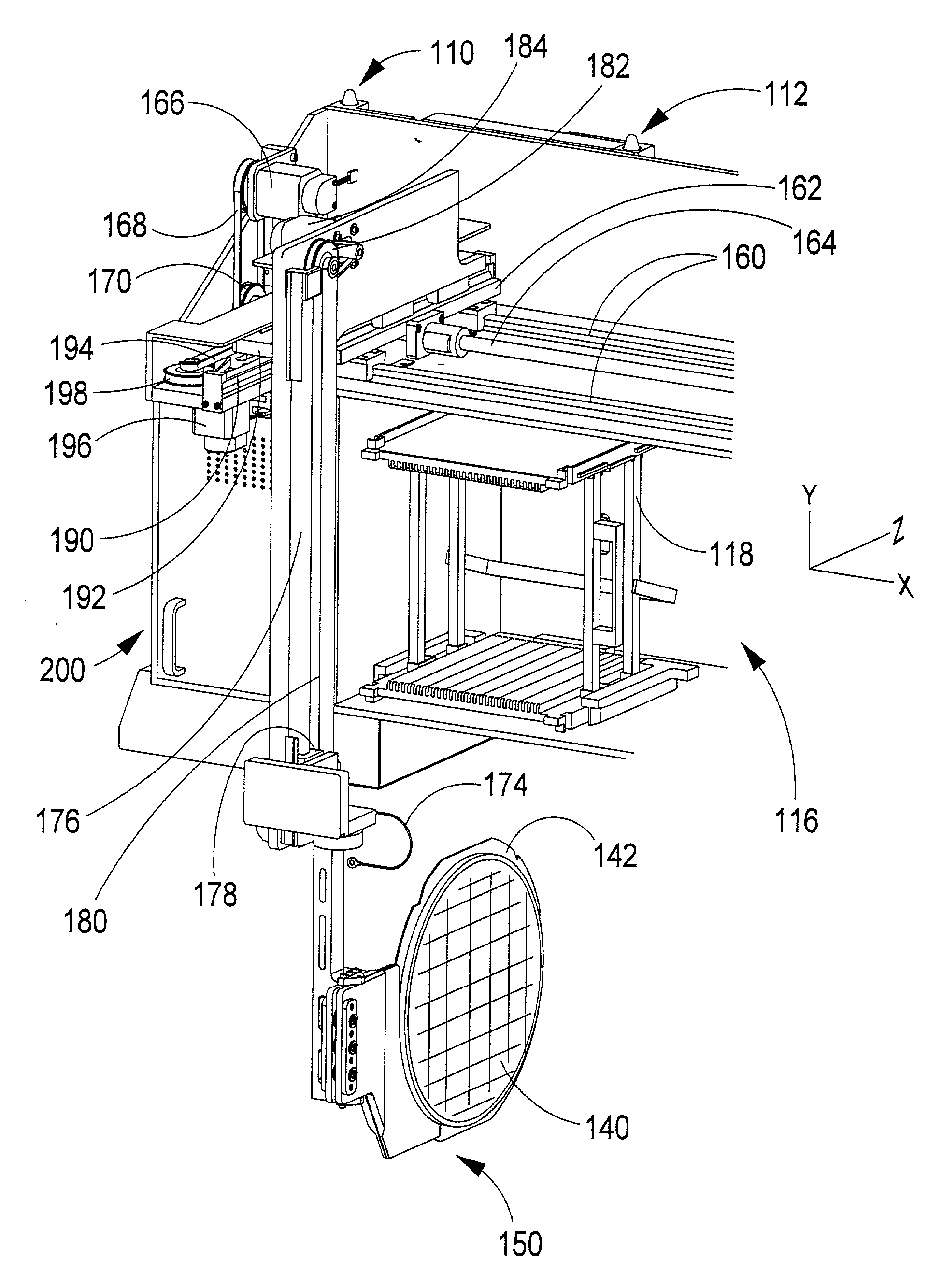
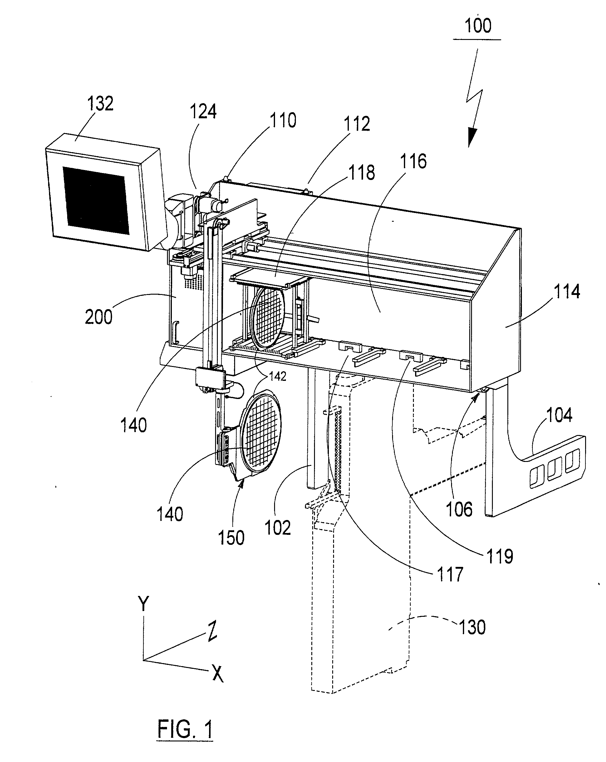
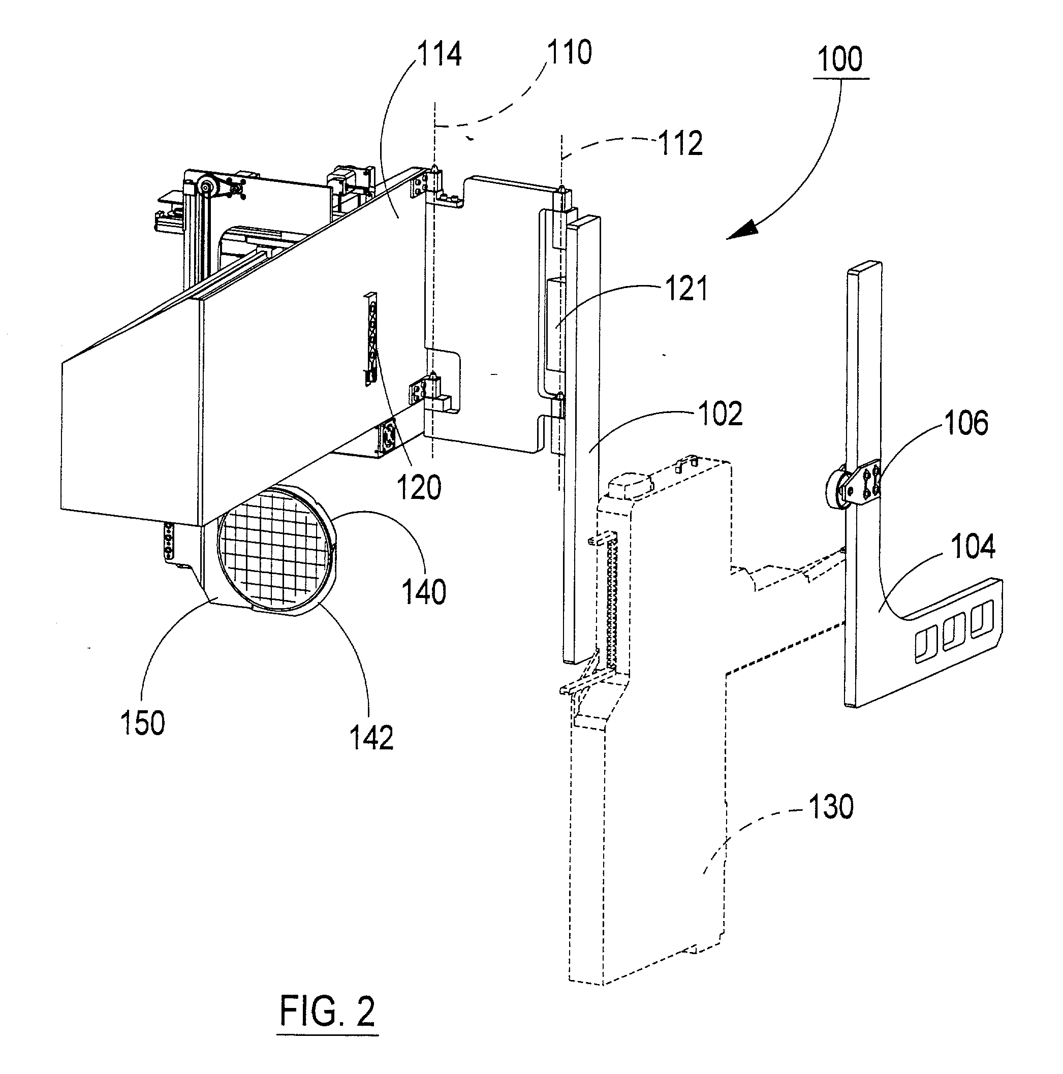
[0023] FIG. 1 depicts a perspective view of an embodiment of the component source interchange gantry 100 in an operating position as it may be configured for use as a supply of wafers for a direct die feeder. FIG. 2 depicts the same component source interchange gantry in an "open" position where it would allow access to an associated component feeder 130. Referring to FIGS. 1 and 2, frame support members 102 and 104 are intended to be integrally affixed to the frame or structure of a component pick-and-place assembly system (not shown). Frame member 102 preferably includes pivot axis 1 10 and 112 about which the storage bay and gantry frame 114 is hingedly affixed to the member 102. In one embodiment, the pivots provide a means for moving said gripper and gantry assembly away from the compon...


PUM


Abstract

The present invention is a method and apparatus for automatically storing and replenishing expandable wafers used in component feeders used in automated printed circuit board assembly systems, for example the Hover-Davis Direct Die Feeder (DDF). In the mass production of printed circuit boards automated pick-and-place equipment accepts die from "chip feeders" and then mounts them at a predetermined location on the circuit board. The present invention includes a wafer or tape reel storage bay and a gripping assembly that is moved by a gantry robot to retrieve a wafer or reel from the storage bay and automatically deposit it into a component feeder.

Description

CROSS REFERENCE[0001] The following related patents and co-pending applications are hereby incorporated by reference for their teachings: p1 "WAFER INTERCHANGE GANTRY," a U.S. Provisional Application for Patent by P. Davis et al., 60 / 216,855, filed Jul. 7, 2000;[0002] "METHOD AND APPARATUS FOR REMOVING DIE FROM AN EXPANDED WAFER AND CONVEYING DIE TO A PICKUP LOCATION," Peter Davis et al., U.S. Pat. No. 5,976,306, issued Nov. 2,1999;[0003] "METHOD AND APPARATUS FOR REMOVING DIE FROM A WAFER AND CONVEYING DIE TO A PICKUP LOCATION," by Peter Davis et al., U.S. application No. 09 / 251,541, filed Feb. 17,1999. (HD-DDF-3); "METHOD AND APPARATUS FOR REMOVING DIE FROM A WAFER AND CONVEYING DIE TO A PICKUP LOCATION," by Peter Davis et al., WO / 99 / 42289 (PCT-US99 / 03385), filed Feb. 17,1999;[0004] "DIE SHUTTLE CONVEYOR AND NEST THEREFOR," by Peter Davis et al., U.S. patent application No. 09 / 684,189, filed Oct. 6, 2000 (formerly U.S. Provisional Application No. 60 / 158,413, filed Oct. 7,1999); an...

Claims


Application Information

Patent Timeline
IPC IPC(8): H01L21/00H01L21/673H01L21/677
CPCH01L21/67144H01L21/67326H01L21/67748H01L21/67751H01L21/67766H01L21/67769
Inventor DAVIS, PETERTARRANT, DEANSUMMERS, MICHAEL A.
Owner DELAWARE CAPITAL FORMATION
Why Eureka
Try Eureka