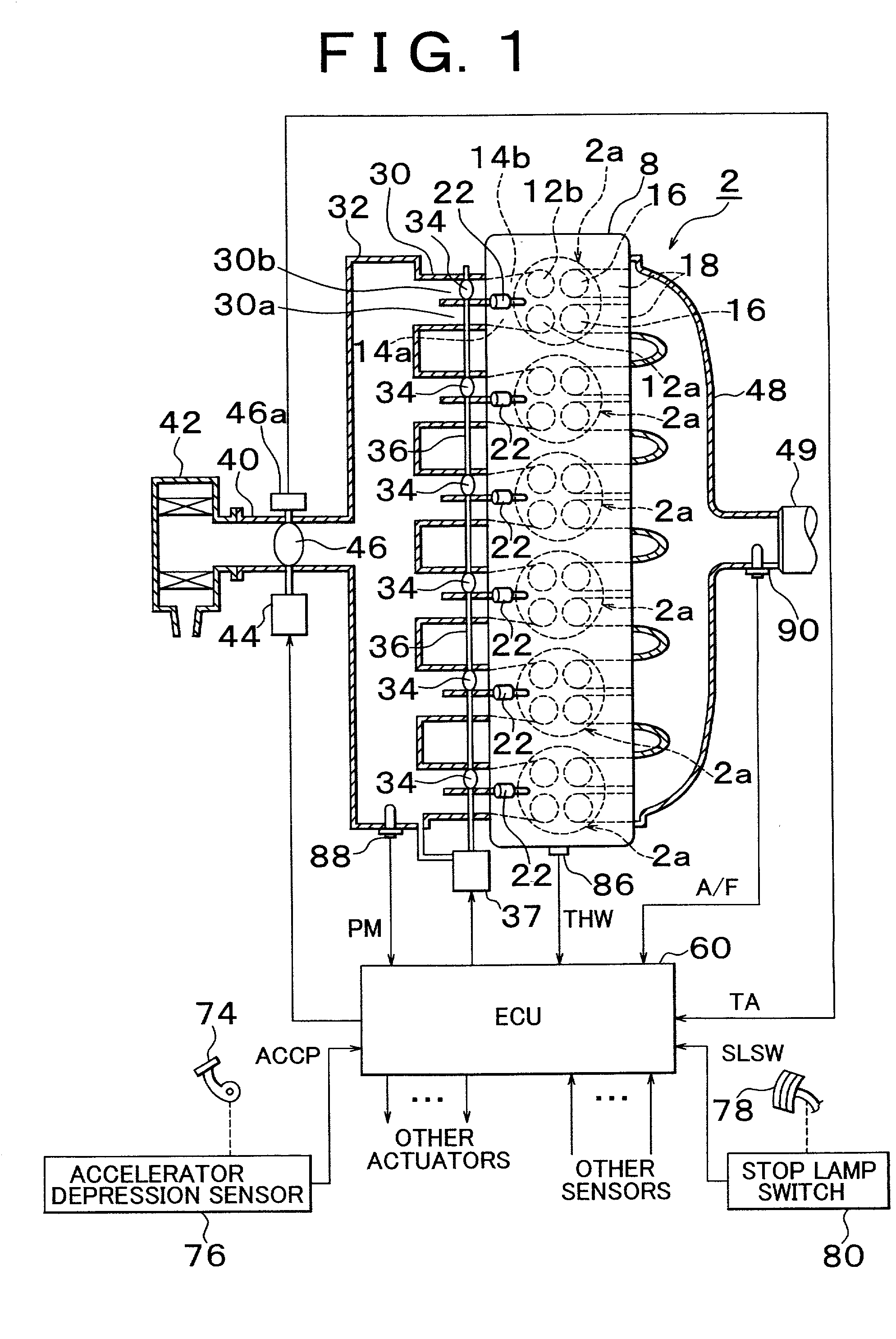
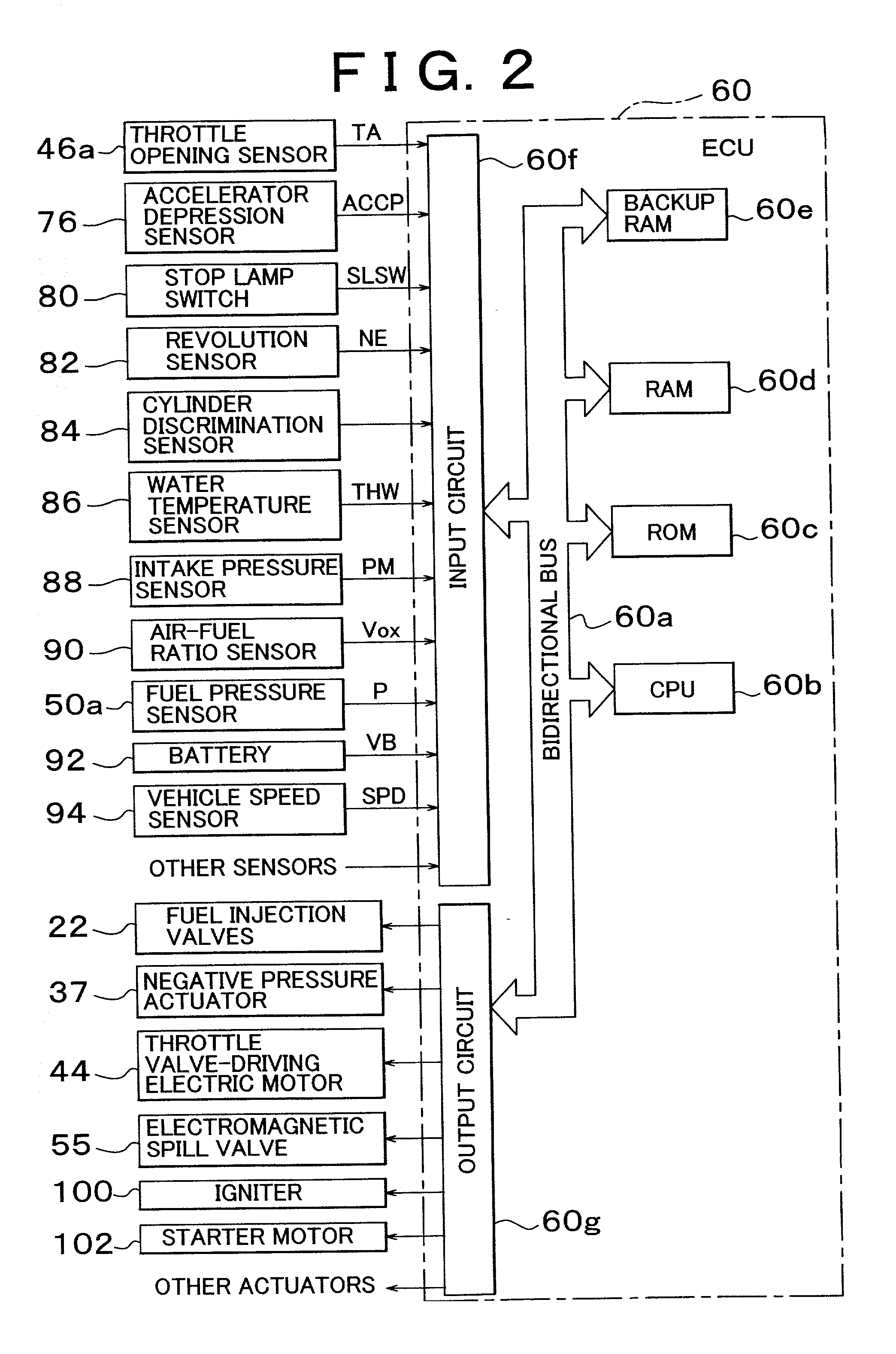
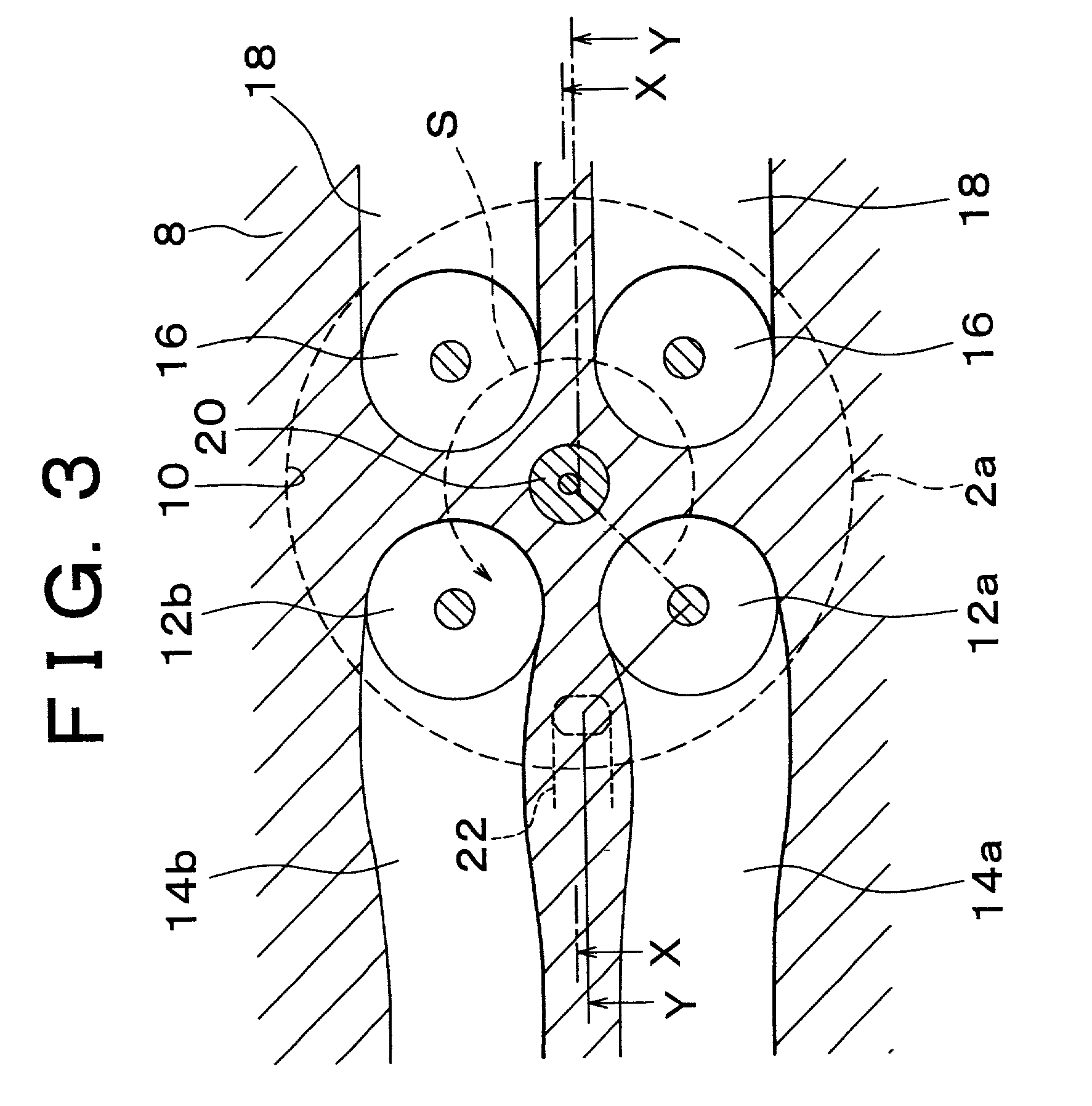
Direct injection type internal combustion engine control apparatus and control method of the same
a technology of control apparatus and control method, which is applied in the direction of electric control, engine starters, machines/engines, etc., can solve the problems of slow fuel supply, slow fuel supply, and slow fuel supply
- Summary
- Abstract
- Description
- Claims
- Application Information
AI Technical Summary
Benefits of technology
Problems solved by technology
Method used
Image
Examples
embodiment 1
[0130] The changing of the fuel pressure P in accordance with Embodiment 1 is illustrated in the timing chart of FIG. 19.
[0131] For example, when the operating person stops the vehicle and keeps it in an idling state at an intersection or the like, the automatic stop condition is met at time point t0. That is, if "YES" in S420, the process proceeds to S430, in which the immediately-before-automatic-stop flag XPREEC is set to "ON". As a result, in S220 and S230, the control duty DT of the electromagnetic spill valve 55 is set to 100%, and the fuel pressure P rapidly rises beyond a during-idle fuel pressure control range (8 to 10 MPa in this embodiment) as indicated by a solid line, and reaches the set valve opening pressure of the relief valve 54g (14 to 14.5 MPa in this embodiment). Therefore, the relief valve 54g temporarily opens to discharge an excess amount of fuel from the fuel distribution pipe 50 into the discharge path 54h. After that, in S460 and S470, the engine 2 is autom...
first embodiment
[0136] The first embodiment as described above achieves the following advantages.
[0137] (1-1) Due to the process of S220, S230, S430, S440 and S450, the fuel pressure P is raised immediately prior to the automatic stop. Therefore, after the engine 2 stops and the delivery of high-pressure fuel from the high-pressure fuel pump 54 toward the fuel injection valves 22 stops, the pressure fall starts from an increased fuel pressure P in comparison with the case where the engine 2 is stopped with an ordinary fuel pressure state as in the conventional art. Therefore, an increased engine stop time is allowed before the fuel pressure decreases to a fuel pressure that makes it impossible to perform appropriate fuel injection into each combustion chamber 10 during the compression stroke. According to the first embodiment, the period between time points t1 and t3 is the period during which it is possible to perform appropriate fuel injection into each combustion chamber 10 during the compressio...
second embodiment
[0144] A second embodiment differs from Embodiment 1 described above in the length of the pressure raise continuation duration Tx related to step S440 of the automatic stop control process (FIG. 17). Other constructions of the second embodiment are the same as those of the first embodiment. That is, in addition to increasing the fuel pressure P to or above the set valve opening pressure of relief valve 54g immediately prior to the automatic stop, the second embodiment, after the set valve opening pressure of the relief valve 54g is reached or exceeded, keeps the control duty DT of the electromagnetic spill valve 55 at 100% until a certain amount of fuel is discharged from the fuel distribution pipe 50 via the relief valve 54g. Therefore, the pressure raise continuation duration Tx is set longer in this embodiment than in the first embodiment.
[0145] As a result, the relief valve 54g is opened repeatedly during a period Tmax as indicated in the timing chart of FIG. 20. That is, while ...
PUM
 Abstract
Description
Claims
Application Information
 - R&D
- Intellectual Property
- Life Sciences
- Materials
- Tech Scout
- Unparalleled Data Quality
- Higher Quality Content
- 60% Fewer Hallucinations
Browse by: Latest US Patents, China's latest patents, Technical Efficacy Thesaurus, Application Domain, Technology Topic, Popular Technical Reports.
© 2025 PatSnap. All rights reserved.Legal|Privacy policy|Modern Slavery Act Transparency Statement|Sitemap|About US| Contact US: help@patsnap.com


